


13–8–612 Page 33
SECTION 9
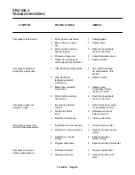
TROUBLE SHOOTING
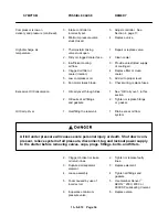
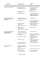
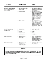
SYMPTOM
POSSIBLE CAUSE
REMEDY
Compressor fails to start.
1.
Wrong lead connections.
1.
Change leads.
2.
Blown fuses in control
2.
Replace fuse.
box.
3.
Motor starter overload
3. Reset and investigate
heaters tripped.
cause of overload.
4.
Pressure in reservoir.
4.
Inspect blowdown valve.
5.
Read error message on
5.
Replace switch.
control panel. See Section 4.
Compressor starts but
1.
High discharge temperature.
1.
See “High Discharge
stops after a short time.
Air Temperature,” this
section.
2.
High discharge
2.
Replace switch.
temperature
switch
malfunction.
3.
Blown fuse in starter/
3.
Replace fuse
control box.
(investigate if fuses
continue to blow).
4.
Motor starter overload
4.
Reset and investigate
heaters trip.
cause of overload.
Compressor does not
1.
Improperly adjusted
1.
Refer to Section 4, page
unload (or load).
control.
19, and adjust control.
2.
Air leak in control
2.
Determine source of
lines.
leak and correct.
3.
Restricted control line.
3.
Clean control lines.
Compressor cycles from
1.
Insufficient receiver capacity.
1.
Increase receiver size.
load to unload excessively.
2.
Restriction in service piping.
2.
Inspect and clean service
piping.
3. Restriction in control
3.
Inspect and clean
tubing.
control tubing.
4.
Plugged aftercooler.
4.
Inspect and clean aftercooler.
Compressor is low on
1.
Restricted air filter.
1.
Clean or replace filter.
delivery and pressure.
2.
Sticking inlet valve.
2.
Inspect and clean inlet
valve.
Содержание EBB BB-7.5 HP
Страница 12: ...13 8 612 Page 2 FIGURE 1 2 PACKAGE COMPRESSOR MOTOR SIDE FIGURE 1 3 PACKAGE BELT GUARD SIDE...
Страница 13: ...13 8 612 Page 3 FIGURE 1 4 PACKAGE CONTROLLER END...
Страница 16: ...13 8 612 Page 6 DECALS 206EAQ077 212EAQ077 218EAQ077 211EAQ077 207EAQ077...
Страница 17: ...13 8 612 Page 7 DECALS 216EAQ077 217EAQ077 222EAQ077 221EAQ077 208EAQ077...
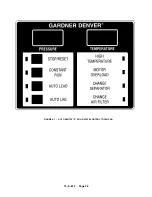
Страница 32: ...13 8 612 Page 22 FIGURE 4 7 AUTO SENTRY S SOLID STATE CONTROL TOUCH PAD...
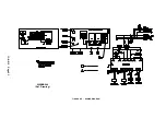
Страница 33: ...13 8 612 Page 23 200EBB546 Ref Drawing FIGURE 4 8 WIRING DIAGRAM...
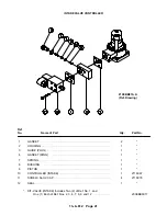
Страница 53: ...13 8 612 Page 43 PIPING AND MOUNTING GROUP 213EBB810 B Ref Drawing...
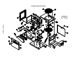
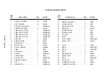
Страница 61: ...13 8 612 Page 51 ELECTRICAL GROUP 205EBB810 A Ref Drawing For Parts List Refer to Pages 52 thru 54...
Страница 72: ...13 8 612 Page 62 FIGURE 11 4 REFRIGERATED DRYER FIGURE 11 5 SUCTION PRESSURE GAUGE DRYER INLET AND OUTLET...
Страница 73: ...13 8 612 Page 63 FIGURE 11 6 CONDENSER HEAT EXCHANGER HOT GAS BYPASS FIGURE 11 7 COMPRESSOR REFRIGERATED DRYER...
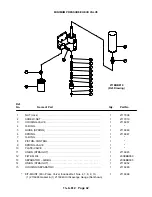
Страница 77: ...13 8 612 Page 67 INTEGRATED DRYER ASSEMBLY AND PIPING 301EBB810 A Ref Drawing...
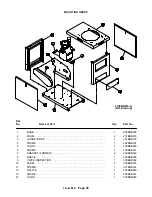
Страница 82: ...13 8 612 Page 72 300EBB541 B Ref Drawing...
Страница 84: ......


