


13–8–612 Page 30
SECTION 6
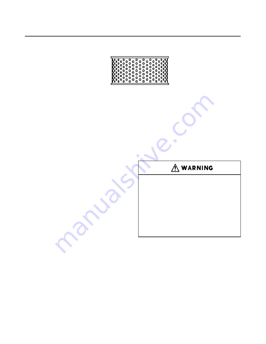
AIR FILTER
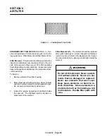
FIGURE 6–1 – STANDARD DUTY AIR FILTER
STANDARD DUTY AIR FILTER (FIGURE 6–1) – Ser-
vice and replacement instructions are given in the fol-
lowing sections: Filter Element and Filter Element Life.
Filter Element – The element should be serviced when
inspection indicates an accumulation of dirt on the out-
side of the element. Clean every 100 to 500 operating
hours depending on dust conditions. Inspect every few
days until experience determines the proper time inter-
val for servicing.
To Service:
1.
Remove element from filter housing.
2.
Blow off excess dirt with air nozzle. Direct air blast
parallel to element pleats at a slight upward angle.
Do not point air blast directly at element.
3.
Inspect for rupture by placing a bright light inside
the element. The slightest rupture requires re-
placement of the element.
Filter Element Life – The element should be replaced
after eight cleanings or if visual inspection indicates a
rupture, crack or pin hole in the pleated media. Inspec-
tion should be done by placing a bright light inside the
element.
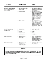
Do not oil this element. Never operate
unit without element. Never use ele-
ments that are damaged or ruptured.
Never use elements that won’t seal.
Keep spare elements on hand to re-
duce downtime. Store elements in a
protected area free from damage, dirt
and moisture. Handle filter parts with
care.
Содержание EBB BB-7.5 HP
Страница 12: ...13 8 612 Page 2 FIGURE 1 2 PACKAGE COMPRESSOR MOTOR SIDE FIGURE 1 3 PACKAGE BELT GUARD SIDE...
Страница 13: ...13 8 612 Page 3 FIGURE 1 4 PACKAGE CONTROLLER END...
Страница 16: ...13 8 612 Page 6 DECALS 206EAQ077 212EAQ077 218EAQ077 211EAQ077 207EAQ077...
Страница 17: ...13 8 612 Page 7 DECALS 216EAQ077 217EAQ077 222EAQ077 221EAQ077 208EAQ077...
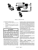
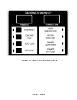
Страница 32: ...13 8 612 Page 22 FIGURE 4 7 AUTO SENTRY S SOLID STATE CONTROL TOUCH PAD...
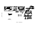
Страница 33: ...13 8 612 Page 23 200EBB546 Ref Drawing FIGURE 4 8 WIRING DIAGRAM...
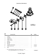
Страница 53: ...13 8 612 Page 43 PIPING AND MOUNTING GROUP 213EBB810 B Ref Drawing...
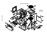
Страница 61: ...13 8 612 Page 51 ELECTRICAL GROUP 205EBB810 A Ref Drawing For Parts List Refer to Pages 52 thru 54...
Страница 72: ...13 8 612 Page 62 FIGURE 11 4 REFRIGERATED DRYER FIGURE 11 5 SUCTION PRESSURE GAUGE DRYER INLET AND OUTLET...
Страница 73: ...13 8 612 Page 63 FIGURE 11 6 CONDENSER HEAT EXCHANGER HOT GAS BYPASS FIGURE 11 7 COMPRESSOR REFRIGERATED DRYER...
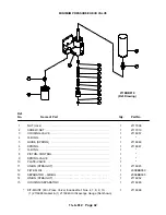
Страница 77: ...13 8 612 Page 67 INTEGRATED DRYER ASSEMBLY AND PIPING 301EBB810 A Ref Drawing...
Страница 82: ...13 8 612 Page 72 300EBB541 B Ref Drawing...
Страница 84: ......


