


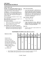


13–8–612 Page 24
SECTION 5
LUBRICATION
OIL COOLER, OIL FILTER & SEPARATOR
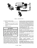
COMPRESSOR OIL SYSTEM (FIGURE 4–1, page
15) The compressor oil system cools the compressor,
lubricates moving parts and seals internal clearances
in the compression chamber.
Air pressure in the oil reservoir forces oil through the oil
cooler, thermostatic mixing valve, oil filter and into the
compressor main oil gallery.
The oil passes through internal passages for lubrica-
tion, cooling and sealing. The air–oil mixture is then
discharged to the oil reservoir where a large part of
the entrained oil drops out of the air stream; the air
then passes through the final oil separator where most
of the remaining oil is removed. The separated oil is re-
turned to the compressor and the air passes to the final
discharge line.
RECOMMENDED LUBRICANT – Gardner Denver
R
compressors are factory filled with AEON
t
lubricants.
These lubricants are formulated to the highest quality
standards and are factory authorized, tested and ap-
proved for use in rotary screw compressors. AEON
t
lubricants are available through your authorized Gar-
dner Denver compressor distributor.
OIL SPECIFICATIONS – The recommended com-
pressor lubricant is Gardner Denver
R
AEON
t
2000
Lubricating Coolant which can be used for year–round
operation except as noted in the “High Temperature
Operation” paragraph, page 25, or low temperature,
see “Installation for Cold Weather,” Section 2, page 10.
AEON
t
2000 Lubricating Coolant is a superior petro-
leum base lubricant formulated and containing addi-
tives for use in Gardner Denver
R
compressors.
Use of improper lubricants will cause
damage to equipment. Do not mix dif-
ferent types of lubricants or use in-
ferior lubricants. Check the decal on
the oil reservoir for lubricating cool-
ant specification.
FIGURE 5–1 – OIL FILL
MAXIMUM (FULL)
MINIMUM (ADD)
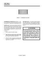
PROCEDURE FOR ADDING/CHECKING OIL LEV-
EL AND CHANGING THE OIL – Check the oil level
before starting the unit and after every 100 hours of op-
eration.
1.
Be sure the unit is completely off and that no air
pressure is in the oil reservoir.
2.
Disconnect, tag and lockout the power supply to
the starter.
3.
Wipe away all dirt around the oil filler plug.
4.
Remove the oil filler plug and add oil as required
to return the oil level to the chamfer at the top of
the filler neck (see FIGURE 5–1, above). The oil
filler plug is provided with a lateral safety hole,
from which oil or air will appear if the oil reservoir
has not been completely blown down.
5.
Install the oil filler plug, run the unit and check for
leaks.
DO NOT OVERFILL. The quantity required to raise
the oil level from “MINIMUM” to “MAXIMUM” is shown
in FIGURE 5–1. Repeated addition of oil between oil
changes may indicate excessive oil carry–over and
should be investigated.
Use only clean containers and funnels so no dirt enters
the reservoir. Provide for clean storage of oils. Chang-
ing the oil will be of little benefit if done in a careless
manner.
Содержание EBB BB-7.5 HP
Страница 12: ...13 8 612 Page 2 FIGURE 1 2 PACKAGE COMPRESSOR MOTOR SIDE FIGURE 1 3 PACKAGE BELT GUARD SIDE...
Страница 13: ...13 8 612 Page 3 FIGURE 1 4 PACKAGE CONTROLLER END...
Страница 16: ...13 8 612 Page 6 DECALS 206EAQ077 212EAQ077 218EAQ077 211EAQ077 207EAQ077...
Страница 17: ...13 8 612 Page 7 DECALS 216EAQ077 217EAQ077 222EAQ077 221EAQ077 208EAQ077...
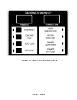
Страница 32: ...13 8 612 Page 22 FIGURE 4 7 AUTO SENTRY S SOLID STATE CONTROL TOUCH PAD...
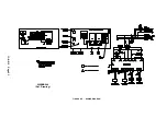
Страница 33: ...13 8 612 Page 23 200EBB546 Ref Drawing FIGURE 4 8 WIRING DIAGRAM...
Страница 53: ...13 8 612 Page 43 PIPING AND MOUNTING GROUP 213EBB810 B Ref Drawing...
Страница 61: ...13 8 612 Page 51 ELECTRICAL GROUP 205EBB810 A Ref Drawing For Parts List Refer to Pages 52 thru 54...
Страница 72: ...13 8 612 Page 62 FIGURE 11 4 REFRIGERATED DRYER FIGURE 11 5 SUCTION PRESSURE GAUGE DRYER INLET AND OUTLET...
Страница 73: ...13 8 612 Page 63 FIGURE 11 6 CONDENSER HEAT EXCHANGER HOT GAS BYPASS FIGURE 11 7 COMPRESSOR REFRIGERATED DRYER...
Страница 77: ...13 8 612 Page 67 INTEGRATED DRYER ASSEMBLY AND PIPING 301EBB810 A Ref Drawing...
Страница 82: ...13 8 612 Page 72 300EBB541 B Ref Drawing...
Страница 84: ......


