13–8–612 Page 64
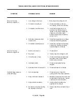
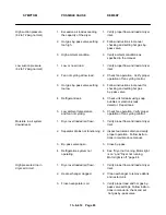
TROUBLE SHOOTING GUIDE FOR OPTIONAL INTEGRATED DRYER
SYMPTOM
POSSIBLE CAUSE
REMEDY
Dryer not running
1.
Low voltage to the dryer.
1. Verify proper line voltage to unit
Motor Run light is on
2.
Contactor not pulling in.
2.
Check all safeties, verify con–
trol voltage, check coil continuity.
3.
Compressor overload open
3.
Verify that compressor is not
grounded or shorted phase to
phase, verify proper refrigerant
charge in unit, verify proper
ambient temperature conditions
(40 to 110 F.).
4.
Defective compressor start
4.
Verify that capacitors and voltage
components.
relays are functioning properly.
5.
Compressor windings open.
5.
Verify that overload is functioning
properly by checking continuity,
read windings for continuity.
Dryer not running
1.
Switch not turned on.
1.
Check switch.
Motor Run light is off.
2.
No power.
2.
Verify proper line voltage to unit.
3.
Circuit breaker or fuse.
3.
Check circuit breakers and fuses.
Ascertain cause of fuse failure
before trying to restart.
4.
Improperly wired.
4.
Check wiring against wiring
diagram.
5.
Defective Start or Stop switch.
5.
Check switches for continuity.
High discharge pressure
1.
Fan not operating.
1.
Check fan motor. Check fan
(above335 psig)
cycling control for proper operation.
2.
Dirty or blocked condensor.
2.
Maintain clearances around the unit
as specified in the manual. Inspect
condensor for dirt and debris.
3.
High ambient conditions.
3.
Verify ambient conditions as
specified in the manual.
4.
Excessive air load exceeding
4.
Verify proper flow and load at dryer
the capacity of the dryer.
inlet.
Содержание EBB BB-7.5 HP
Страница 12: ...13 8 612 Page 2 FIGURE 1 2 PACKAGE COMPRESSOR MOTOR SIDE FIGURE 1 3 PACKAGE BELT GUARD SIDE...
Страница 13: ...13 8 612 Page 3 FIGURE 1 4 PACKAGE CONTROLLER END...
Страница 16: ...13 8 612 Page 6 DECALS 206EAQ077 212EAQ077 218EAQ077 211EAQ077 207EAQ077...
Страница 17: ...13 8 612 Page 7 DECALS 216EAQ077 217EAQ077 222EAQ077 221EAQ077 208EAQ077...
Страница 32: ...13 8 612 Page 22 FIGURE 4 7 AUTO SENTRY S SOLID STATE CONTROL TOUCH PAD...
Страница 33: ...13 8 612 Page 23 200EBB546 Ref Drawing FIGURE 4 8 WIRING DIAGRAM...
Страница 53: ...13 8 612 Page 43 PIPING AND MOUNTING GROUP 213EBB810 B Ref Drawing...
Страница 61: ...13 8 612 Page 51 ELECTRICAL GROUP 205EBB810 A Ref Drawing For Parts List Refer to Pages 52 thru 54...
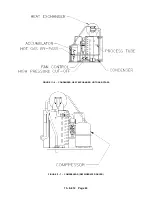
Страница 72: ...13 8 612 Page 62 FIGURE 11 4 REFRIGERATED DRYER FIGURE 11 5 SUCTION PRESSURE GAUGE DRYER INLET AND OUTLET...
Страница 73: ...13 8 612 Page 63 FIGURE 11 6 CONDENSER HEAT EXCHANGER HOT GAS BYPASS FIGURE 11 7 COMPRESSOR REFRIGERATED DRYER...
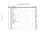
Страница 77: ...13 8 612 Page 67 INTEGRATED DRYER ASSEMBLY AND PIPING 301EBB810 A Ref Drawing...
Страница 82: ...13 8 612 Page 72 300EBB541 B Ref Drawing...
Страница 84: ......


