A26361-K863-Z102-8-7619
Rev. 8.0
103
9
The Switch Blade
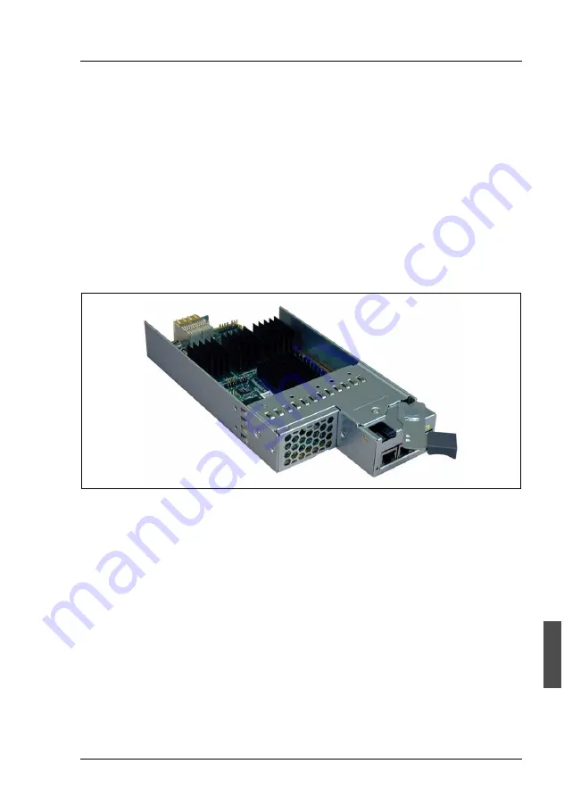
The four hot-swappable redundant switch blades provide high-speed LAN
access via multiple Gigabit interfaces. Each switch blade has ten downlink ports
to the server blades and three uplink ports. These LAN connections provide the
I/O functionality for the server blade. All traffic to and from the system occurs via
Network.
I
The switch blades provide comfortable user interfaces: a web interface is
available as well as a command line interface using the Telnet protocol.
For a detailed description please refer to the manual „LAN Switch Blade
User Interface Description“.
Figure 65: Switch blade
The basic configuration includes one switch blade (slot 1). Depending on the
desired configuration, the system can be upgraded with up to three additional
switch blades. The slots for these blades are numbered from 1 to 4 and are
located on the rear side of the server system, underneath the rear fan module
(see figure 66 on page 104). A maximum of 10 server blades can be accessed
from one switch blade.
The switch blade in slot 1 is connected via the internal midplane to port A of the
server blades located in the corresponding odd-numbered slots (1, 3, 5,...).
If port B of the odd server blades is also to be used, a second switch blade must
be installed in the corresponding slot 3. In this case the switch blades in slot 1
and 3 are redundant.
Содержание PRIMERGY BX300
Страница 4: ......
Страница 6: ......
Страница 10: ......
Страница 20: ......
Страница 47: ...A26361 K863 Z102 8 7619 Rev 8 0 37 Installing the Hardware Cabling the System Figure 12 Cable routing ...
Страница 72: ......
Страница 78: ......
Страница 80: ......
Страница 120: ......
Страница 134: ......
Страница 142: ......
Страница 150: ......
Страница 158: ......
Страница 160: ......
Страница 162: ......


