


System expansions
66
Fujitsu Technology Solutions
2
1
3
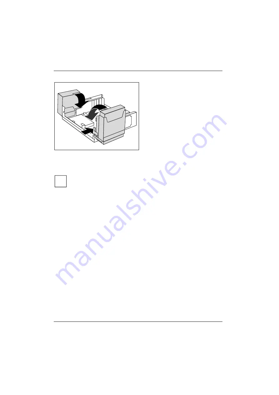
►
Fold down the power supply in the
direction of the arrow (1) until the power
supply engages.
►
Press on the locking lug (2) of the drive
cage and then fold the drive cage with
light pressure in the direction of the
arrow (3) until the lever engages.
Make sure that the cables are not kinked or
pinched.
►
Connect the power supply connector.
►
Replace the cross piece (see "Installing the cross-piece").
►
Close the casing (see "Closing the casing").
i
It may be necessary to modify the entry for the drive in the
BIOS Setup
.
Содержание ESPRIMO E5635
Страница 1: ...ESPRIMO E5635 E5730 ESPRIMO E5731 E7935 ESPRIMO E7936 E9900 Operating Manual System ...
Страница 3: ......
Страница 14: ...Important notes 6 Fujitsu Technology Solutions ...
Страница 30: ...Preparing for use 22 Fujitsu Technology Solutions ...
Страница 84: ...System expansions 76 Fujitsu Technology Solutions ...
Страница 86: ...Technical data 78 Fujitsu Technology Solutions ...


