41
4. Adjustment
FinePix F601 Zoom (U/E/EG) SERVICE MANUAL
4-17. [F9]: DC Jack Voltage Adjustment
(note)
1) When adjusting the DC jack voltage, supply power
(5V) to the camera from the
[Specified Power Cable
Jig]
before setting the jig mode.
2) Always measure input voltage in the vicinity of the
DC IN terminal.
3) When reducing the voltage, adjust the stabilized pow-
er supply to ensure that the voltage is not reduced ex-
cessively from the measured point. The adjustment
software may produce an error if communication be-
tween the adjustment software and the camera is dis-
rupted. Restart the adjustment software in this case.
<Step 1>
Select
[F9]
from
[Adjustment Select Screen (Fig.4)]
(ie
press the [F9] key on the computer).
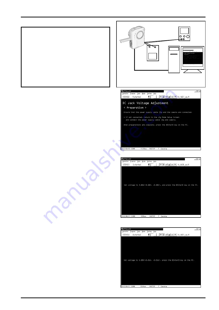
---> The
[DC Jack Voltage Adjustment Preparation Screen
(Fig.28)]
is displayed.
<Step 2>
Follow the instructions on the [DC Jack Voltage Adjust-
ment Preparation Screen (Fig.28)], and ensure that the
power cable jig and the camera are connected.
* If not connected, return to the Jig Mode Setup Screen
and connect the power cable jig and camera.
When preparations are complete, press the [Enter] key
on the computer.
---> The
[5.80V Input Screen (Fig.29)]
is displayed.
<Step 3>
Follow instructions on the [5.80V Input Screen (Fig.29)],
and adjust DC_V2 high voltage.
Set voltage to 5.80V
(+0.02V, -0.00V)
, and press the [En-
ter] key on the computer.
---> The
[5.00V Input Screen (Fig.30)]
is displayed.
<Step 4>
Follow instructions on the [5.00V Input Screen (Fig.30)],
and adjust DC_REF voltage.
Set voltage to
5.00V(+0.01V, -0.01V)
, press the [Enter]
key on the computer.
---> Save the adjusted data to the flash ROM.
---> The
[DC Jack Voltage Adjustment Complete Screen
(Fig.31)]
is displayed when the adjusted data is saved
normally.
USB cable
Digital voltmeter
Connections for DC Jack Voltage Adjustment
+ -
Stabilized power supply
DC_5V
<Fig.28> DC Jack Voltage Adjustment Preparation Screen
<Fig.29> 5.80V Input Screen
<Fig.30> 5.00V Input Screen


