background image

Section 5 Component Teardown

5-5

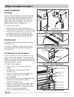
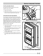
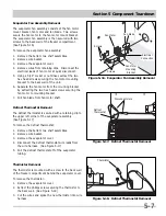
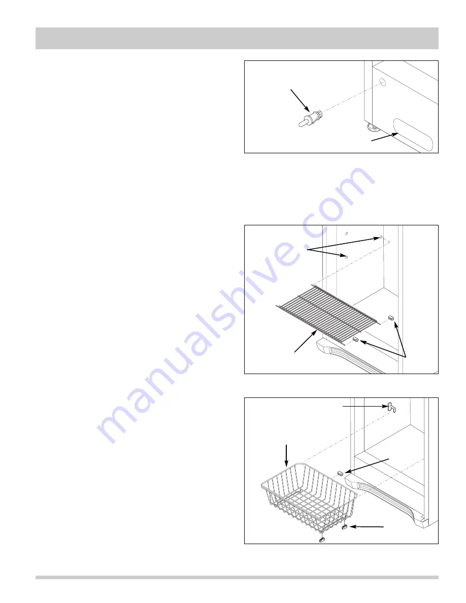
Figure 5-10.  Door Switch Removal

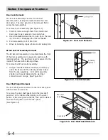
Figure 5-11.  Shelf Assembly Removal

Door Switch Removal

The door switch is mounted inside a hole in the 
cabinet base along the lower left hand side. 
(See Figure 5-10)

To remove the door switch:  

1. Remove 

kickplate.

2. Reach into the access hole next to the door switch

and disconnect the electrical leads from the door
switch terminals.  

3. Press in on the retaining latch on the switch body

and push switch through hole in cabinet base.

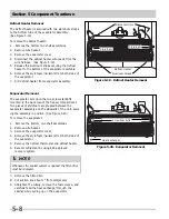
Interior Components

Shelf Assembly

The shelf assemblies have metal bars that slide into
holes in the cabinet interior liner walls.  Rubber bumpers
are attached to the metal bars to prevent side to side
movement within the cabinet.  (See Figure 5-11)

To remove the shelf assemblies: 

1. Remove rubber bumpers from right side of shelf

assembly.

2. Remove shelf assembly by pushing to the right until

the metal bars are free from the left side liner wall.
Then tilt down or up until the shelf can be removed
from the right side liner wall.

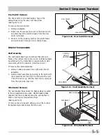
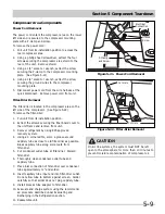
Wire Basket Removal

The wire basket slides under the basket stops mounted
to the compartment side walls.  Plastic basket glides
clipped onto the wire basket allow the wire basket to
slide on the freezer compartment floor. 
(See Figure 5-12)

To remove the wire basket, simply pull out from under
the basket stops and remove from the unit.

Door Switch

Locating

Holes in

Liner Wall

Access Hole

Wire Shelf

Bumper

Figure 5-12.  Wire Basket Removal

Wire Basket

Basket Stop

Bumper

Basket
Glide

Содержание FFH17F8HW0

Страница 1: ...All about Servicing Upright Freezers With Standard And Electronic Controls Publication 5995531505 January 2009 Electrolux Major Appliances North America 250 Bobby Jones Expwy Augusta GA 30907 ...

Страница 2: ......

Страница 3: ... is GREEN or GREEN with YELLOW STRIPES Ground leads are not to be used as current carrying conductors It is EXTREMELY important that the service technician reestablish all safety grounds prior to completion of service Failure to do so will create a hazard 7 Prior to returning the product to service ensure that All electrical connections are correct and secure All electrical leads are properly dres...

Страница 4: ...2 Basic Components 4 2 Refrigerant Cycle 4 2 Low High Side Leak or Undercharge 4 3 Testing for Refrigerant Leaks 4 3 Compressor Replacement 4 3 To Flush the System 4 4 To Use Dry Nitrogen to Flush the System 4 4 To Use Refrigerant to Flush the System 4 4 Installing a New Compressor 4 5 Condenser Replacement 4 6 Filter Drier Installation 4 7 Evaporator and Suction Line Replacement 4 7 Equipment Nee...

Страница 5: ... Shelf Guard 5 4 Door Switch 5 5 Interior Components 5 5 Shelf Assembly 5 5 Wire Basket 5 5 Light Shield 5 6 Light Fixture 5 6 Baffle Plate 5 6 Evaporator Cover 5 6 Evaporator Fan Assembly 5 7 Defrost Thermostat 5 7 Thermistor 5 7 Defrost Heater 5 8 Evaporator 5 8 Compressor Area Components 5 9 Power Cord 5 9 Filter Drier 5 9 Drain Pan 5 9 Compressor 5 10 Condenser Service 5 11 Section 6 Troublesh...

Страница 6: ...furniture An empty discarded ice box refrigerator or freezer is a very dangerous attraction to children Remove and discard any spacers used to secure the shelves during shipping Small objects are a choke hazard to children Remove the door s of any appliance that is not in use even if it is being discarded Risk of Child Entrapment Child entrapment and suffocation are not problems of the past Junked...

Страница 7: ...of Defrost Product Type Product Brand Brand F F H 17 F 8 H W Product Size AF Frigidaire Ultrafreeze LF Lowe s Frigidaire F Frigidaire GL Frigidaire Gallery G Gibson PL Frigidaire Professional W White Westinghouse FK Kenmore Frigidaire K Kelvinator Section 1 Basic Information 1 5 Serial Plate The serial plate is located inside the cabinet on the left sidewall The technician should always refer to t...

Страница 8: ...nt Running Time 30 45 45 65 Wattage Range Last 1 3 of cycle 100 140 110 145 Suction Pressure Cut in cut out PSIG 14 0 14 0 High Side Pressure Last 1 3 of cycle PSIG 100 125 140 165 28 32 59 min 60 max 26 55 31 with door 90 open Note To allow for proper airflow airspace required on each side back and top Power cord location right bottom rear minumum surrounding 3 Model FFH17F8W Unit Dimensions ...

Страница 9: ...use an adapter plug Do not use an extension cord Do not use a power cord that is frayed or damaged The use of a ground fault interrupter GFI is not recommended Do not install or use a damaged appliance If you receive a damaged appliance immediately contact your dealer or builder The installer must show the customer the location of the power plug so that they know where and how to disconnect power ...

Страница 10: ... suffocation are not problems of the past Junked or abandoned refrigerators or freezers are still dangerous even if they will sit for just a few days If you are getting rid of your old refrigerator or freezer please follow the instructions below to help prevent accidents Remove the door lid Leave shelves in place so children may not easily climb inside Have the refrigerant removed by a qualified t...

Страница 11: ...wer front of your freezer Sufficient air circulation is essential for the proper operation of your freezer Leveling The freezer must have all bottom corners resting firmly on a solid floor The floor must be strong enough to support a fully loaded freezer It is VERY IMPORTANT for your freezer to be level in order to function properly If the freezer is not leveled during installation the door lid ma...

Страница 12: ...ion against shock haz ards It must be plugged directly in to its own properly grounded three prong receptacle protected with a 15 amp time delay fuse or circuit breaker The receptacle must be installed in accordance with the local codes and ordinances Consult a qualified electrician Receptacles with Ground Fault Circuit Interrupters GFCI are NOT RECOMMENDED DO NOT USE AN EXTENSION CORD OR AN ADAPT...

Страница 13: ...utlet 2 Gently lay freezer on its back on a soft clean surface 3 Lift plastic cover off upper hinge assembly See Figure 2 4 4 Using a T27 tamper proof Torx bit extract screws securing the upper hinge to the unit frame 5 Remove the grille kickplate by extracting the screws from each end of the grille kickplate Remove wire from clips on bottom of cabinet See Figure 2 5 6 Reach under bottom of cabine...

Страница 14: ...Section 2 Installation Information 2 6 Notes ...

Страница 15: ...eset for 3 seconds For the first second U will appear and then the current temperature setting will appear Defrost Timing After each 12 hours of accumulated compressor run time 30 minutes of defrost will begin During these 30 minutes the defrost heater will run until the termination switch opens After the thirty minutes the compressor will run Manual Defrost To manually enter the defrost mode turn...

Страница 16: ...en C for close or for good thermistor for three seconds 7 10 seconds for power check During this time each key activates a specific load a UP key activates the compressor and lowercase c is displayed b DOWN key activates defrost heater and lowercase d is displayed 8 MUTE key activates the light and lowercase l is displayed 10 seconds after the last key press the system will exit the diagnostic mod...

Страница 17: ...d off when the ALARM RESET button is pressed but the High Temp LED will remain lit until the temperature is again below 23ºF Instructions for Programming EZ Set Controls Programming is determined by Model size Your Model size is shown on the serial plate inside the freezer as Type 14F 17F 21F After plugging in the unit wait for the display to flash the type Number 1 1 For type U17F models use this...

Страница 18: ...Section 3 Electronic Control 3 4 Notes ...

Страница 19: ...propriate product specifications are met This term usually implies the use of processes or procedures available only at a reprocessing or manufacturing facility Safety Warnings Compressor Testing Whenever testing a compressor extreme caution should be used to prevent damaging the terminals A compressor with a damaged terminal or a grounded winding can expel a terminal from its insulated housing wh...

Страница 20: ...t occurs whenever the compressor is in operation Liquid refrigerant is evaporated in the evaporator by the heat that enters the cabinet through the insulated walls and by the heat from product load and door openings The refrigerant vapor is then drawn from the evaporator through the suction line to the compressor Compression raises the pressure and temperature of the vapor in the compressor and th...

Страница 21: ... of refrigerant and the system has not been recently opened there is probably a leak in the system Adding refrigerant without first locating and repairing the leak or replacing the component will not permanently correct the difficulty The leak must be found Sufficient refrigerant may have escaped to make it impossible to leak test effectively In such cases add a line piercing valve to the compress...

Страница 22: ...ntil discharge into bag is clear 4 Disconnect capillary tube from evaporator Flush evaporator in same manner as condenser 5 Flush cap tube This is only possible if you have proper service valve adapter 6 Reassemble system Use extreme care when using Dry Nitrogen to flush systems Pressure in nitrogen cylinder could be as high as 2000 psi Nitrogen cylinder must be equipped with approved pressure reg...

Страница 23: ...o the compressor shell A high side process tube is attached to the filter drier Replacement compressors for refrigerators may have an oil cooler even if the original compressor did not If the product is not equipped for an oil cooler leave the plastic caps in place and install the compressor connecting only to the suction and discharge lines of the new compressor Before installing the replacement ...

Страница 24: ... 0 5 to provide sufficient area for good solder joint Clean and mark area where tubing should be cut Cut tub ing with tubing cutter Work as quickly as possible to avoid letting moisture and air into the system 11 Solder all connections according to soldering procedure 12 Remove original filter drier 13 Install new filter drier at condenser outlet 14 Evacuate and charge system using recommended pro...

Страница 25: ...ion Line Replacement 1 Disconnect electrical supply to refrigerator 2 Recover refrigerant by using EPA approved recovery system 3 Remove shelving 4 Remove evaporator cover 5 Remove evaporator from its installation position 6 Cut or remove suction line from compressor 7 Cut filter drier from condensing unit 8 Remove sealant from cabinet where suction line enters 9 Remove evaporator and suction line...

Страница 26: ...acuum pump Check the serial plate for the correct refrigerant type It is extremely important to verify the type of refrigerant in the system before starting any sealed system repairs With the possible exception of the vacuum pump all service equipment that comes in contact with R 134a during evacuation and recharging must be dedicated Accordingly R 134a will require a dedicated charging cylinder m...

Страница 27: ...s closed 2 Close high side manifold gauge valve 3 Set charging cylinder scale to pressure indicated on cylinder pressure gauge 4 Observe refrigerant level in sight glass Subtract amount to be charged into system and note shut off point 5 Open charging cylinder valve slowly and allow proper charge to enter system 6 As soon as refrigerant in sight glass has gone down to predetermined level close cha...

Страница 28: ...before proceeding 12 Remove the high side process tube adapter and solder the process tube closed 13 Clamp the low side process tube with the pinch off tool while the unit is running Remove the low side process tube adapter and solder the process tube closed 14 Check the process tubes for refrigerant leaks Final Leak Test 1 With the refrigerator turned OFF leak test all low side system components ...

Страница 29: ...und transmission Miscibility of R 134a and Ester Oil A special synthetic oil known as Ester oil is used as a lubricant in refrigeration systems operating on R 134a Ester oils are produced from alcohols and fatty acids and are available in several different variants Ester oils have a pleasant aroma reminiscent of fruit Ester oils generally include various types of additives for improving certain pr...

Страница 30: ...e of development work on R 134a tests were carried out on a different type of synthetic oil known as Poly Alkaline Glycol PAG This oil is also used in certain air conditioning systems for cars PAG and Ester oil DO NOT mix with one another Service equipment used for R 134a Ester oil must not come into contact with PAG Water In The Refrigeration System Even in very small quantities water in any refr...

Страница 31: ...e leak you will need to install the two stage service dryer filter part number 5303918288 You must heat the crankcase area of the compressor using a heat gun on the high heat setting throughout the 30 minutes you are running your vacuum pump to pull a vacuum on the system Every 4 to 5 minutes while you are running your vacuum pump and heating the crankcase area shake the compressor By heating the ...

Страница 32: ... newly designed detectors with good R 134a sensitivity are now available Be sure to consult with the manufacturer before selecting or using a non selective detector with R 134a Halogen specific detectors use a specialized sensor that allows detection of compounds containing chlorine fluorine bromine and iodine without being activated by other species The major advantage of this type of detector is...

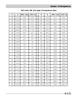
Страница 33: ...Section 4 Refrigeration 4 15 HFC 134a CFC 12 Pressure Temperature Chart ...

Страница 34: ...If breathing has stopped give artificial respiration Spills or Leaks If a large release of vapor occurs such as from a large spill or leak the vapors may concentrate near the floor or low spots and displace the oxygen available for breathing causing suffocation Evacuate everyone until the area has been ventilated Use blowers or fans to circulate the air at floor level DO NOT re enter the affected ...

Страница 35: ... should be monitored routinely Air lines should never be connected to storage tanks Filling and Charging Operations Before evacuating cylinders or refrigeration equipment any remaining refrigerant should be removed by recovery system Vacuum pump discharge lines should be free of restrictions that could increase discharge pressures above 15 psig 205 kPa and result in formation of combustible mixtur...

Страница 36: ...Section 4 Refrigeration 4 18 Notes ...

Страница 37: ...ssor assembly will be hot Wear protective gloves and the appropriate safety gear when working with compressors If removing a door or drawer from a unit remember that the doors and drawers are heavy If they were to fall they could cause serious personal injury WARNING Metal edges may be sharp Use caution and wear appropriate safety equipment when servicing evaporators and condensers to avoid person...

Страница 38: ...Assembly Removal The door assembly is secured to the unit frame by an upper and lower hinge assembly The wiring harness leading out of the door assembly must be disconnected from the wire harness in the compressor area before the door assembly can be removed To remove the door assembly 1 Gently lay freezer on its back on a soft clean surface 2 Lift plastic cover off upper hinge assembly See Figure...

Страница 39: ...n the inner panel and the door assembly and is secured in position when the inner panel screws are fastened to the door assembly The inner panel does not have to be removed to extract the door gasket from the door assembly To remove the door gasket 1 Lift the inside edge of the door gasket to access the inner panel screws 2 Loosen the inner panel screws until the door gasket can be pulled out from...

Страница 40: ... the door assembly and is secured in position with retaining latches The electronic board is secured to the inside of the bezel with retaining latches To remove the EZ Set control assembly 1 Using a small flat bladed screwdriver carefully pry under the bezel until the retaining latches release from the door assembly Pull control assembly straight out to avoid damaging the electrical connection wir...

Страница 41: ...hed to the metal bars to prevent side to side movement within the cabinet See Figure 5 11 To remove the shelf assemblies 1 Remove rubber bumpers from right side of shelf assembly 2 Remove shelf assembly by pushing to the right until the metal bars are free from the left side liner wall Then tilt down or up until the shelf can be removed from the right side liner wall Wire Basket Removal The wire b...

Страница 42: ...ffle plate is secured with four retaining latches to slots in the compartment upper back wall See Figure 5 14 To remove the baffle plate with one hand grab the baffle plate from the center and pull back while with the other hand reach behind to disengage the retaining latches Evaporator Cover Removal The evaporator cover is secured with screws to the back wall and bottom of the freezer compartment...

Страница 43: ...xtracting the two hex head screws securing the fan motor to mounting bracket 7 Pull fan blade from fan motor shaft Defrost Thermostat Removal The defrost thermostat is secured with a retaining clip to the upper left corner of the evaporator assembly See Figure 5 17 To remove the defrost thermostat 1 Remove the bottom two shelf assemblies 2 Remove wire basket 3 Remove the evaporator cover 4 Disconn...

Страница 44: ...partment Two pieces of styrofoam are pressed between the evaporator assembly and the sidewalls of the unit secur ing the assembly in position See Figure 5 20 To remove the evaporator 1 Remove the bottom two shelf assemblies 2 Remove wire basket 3 Remove the evaporator cover 4 Remove the styrofoam insulators from both sides of the evaporator 5 Remove the defrost thermostat and defrost heater 6 Reco...

Страница 45: ...r drier 1 Pull unit from its installation position 2 Extract the screws securing the fiber board cover to the unit frame and remove from unit 3 Recover refrigerant by using EPA approved recovery system 4 Using a 3 cornered file score a groove around capillary tube as close to old filter drier as possible Break capillary tube along score mark from filter drier 5 Cut condenser outlet tube at filter ...

Страница 46: ...remove from unit 3 Using a small flat bladed screwdriver release the locking tab from the wire harness connection and disconnect from compressor controller 4 Using a needlenose pliers remove spring wire holding the controller to the compressor 5 Recover refrigerant by using EPA approved recovery system 6 Using a 7 16 socket remove the 4 bolts one in each corner holding the compressor to the base S...

Страница 47: ...nsists of a condenser assembly that can be installed on the back of the cabinet mounting hardware replacement filter drier and a complete installation instructions To install use the following procedure 1 Disconnect unit from source of power 2 Recover refrigerant by using EPA approved recovery system 3 Installed the replacement condenser in accordance with the instructions included with the kit 4 ...

Страница 48: ...Section 5 Component Teardown 5 12 Notes ...

Страница 49: ...m Use another circuit Check circuit for proper voltage Set control to a temperature setting Instruct customer Ensure plug is tightly pushed into outlet Check replace fuse with a 15 amp time delay fuse Reset circuit breaker Check house lights Call local Electric Company It s normal for the Freezer to work harder under these conditions It takes 24 hours for the Freezer to cool down completely Warm f...

Страница 50: ...ing or cracking sound when compressor comes on Bubbling or gurgling sound Vibrating or rattling noise Moisture forms on inside Freezer walls Odors in Freezer Door will not close Light bulb is not on This is normal When the surrounding noise level is low you might hear the compressor running while it cools the interior This is normal Sound will level off or disappear as Freezer continues to run Thi...

Страница 51: ...1 Defective electronic control 1 Is the control set to zero 1 Check the light bulb with an ohmmeter Is the bulb good 1 Connect a low side gauge to the processing tube on the compressor Is the pressure in a vacuum or lower than normal 1 Defective electronic control 1 Defective electronic control Yes Go to step 2 No Check power to freezer and make sure unit is plugged in Yes Set control from 1 to 7 ...

Страница 52: ...re on the thermostat and the wire at the end of the heater Is the reading about 25 omhs 3 Disconnect defrost thermostat from the defrost heater and measure the resistance of the defrost heater Is the reading about 25 omhs Freezer does not automatically defrost Yes Replace electronic control No Go to step 2 Yes Replace electronic control No Go to step 3 Yes Replace defrost thermostat No Replace def...

Страница 53: ...Section 7 Wiring Diagram 7 1 ...

Страница 54: ...Section 7 Wiring Diagram 7 2 Notes ...

Отзывы: