Section 4 Refrigeration
4-12
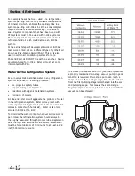
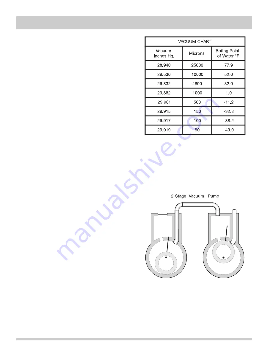
To achieve the required 29.9 inch (500 micron) vacuum,
a properly maintained two-stage vacuum pump in good
condition is required. A two stage pump can reach a
deeper vacuum than a single stage because the exhaust
from the first pumping stage is discharged into the sec-
ond pumping stage. This means the second stage
begins pumping at a lower pressure so a lower ultimate
vacuum can be achieved.
For example, hoses that were used for a refrigeration
system operating on R-12 may contain small quantities
of mineral oil which can block the capillary tube in a
system operating on R-134a. As little as one milligram
may be sufficient to cause a blockage. In addition,
sealed system components that have been used with
CFC systems must not be used with R-134a systems.
These components may contain residual amounts of
refrigerant and oil which could damage an R-134a
system.
At the earliest stage of development work on R-134a,
tests were carried out on a different type of synthetic oil
known as Poly-Alkaline Glycol (PAG). This oil is also
used in certain air conditioning systems for cars.
PAG and Ester oil DO NOT mix with one another. Service
equipment used for R-134a / Ester oil must not come
into contact with PAG.
Water In The Refrigeration System
Even in very small quantities, water in any refrigeration
system can cause the following problems:
•
Ice plugs in capillary tubes.
•
Copper plating in compressor.
•
Reactions with organic materials in systems.
•
Corrosion of metals.
R-134a and Ester oil will aggravate the problem of water
in the refrigeration system. Ester oil may react with
water vapor and is hygroscopic (it will absorb water if it
comes in contact with humid air). Water is also more
soluble in R-134a than R-12.
To minimize the water content whenever service work is
performed, the refrigeration system should always be
thoroughly evacuated through process tube adapters on
both the high and low sides of the system. Evacuation
must be for a minimum of 30 minutes to at least a 29.9
inch (500 micron) vacuum.
Содержание FFH17F8HW0
Страница 2: ......
Страница 14: ...Section 2 Installation Information 2 6 Notes ...
Страница 18: ...Section 3 Electronic Control 3 4 Notes ...
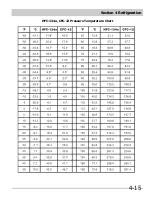
Страница 33: ...Section 4 Refrigeration 4 15 HFC 134a CFC 12 Pressure Temperature Chart ...
Страница 36: ...Section 4 Refrigeration 4 18 Notes ...
Страница 48: ...Section 5 Component Teardown 5 12 Notes ...
Страница 53: ...Section 7 Wiring Diagram 7 1 ...
Страница 54: ...Section 7 Wiring Diagram 7 2 Notes ...

