Section 5 Component Teardown
5-7
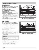
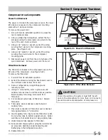
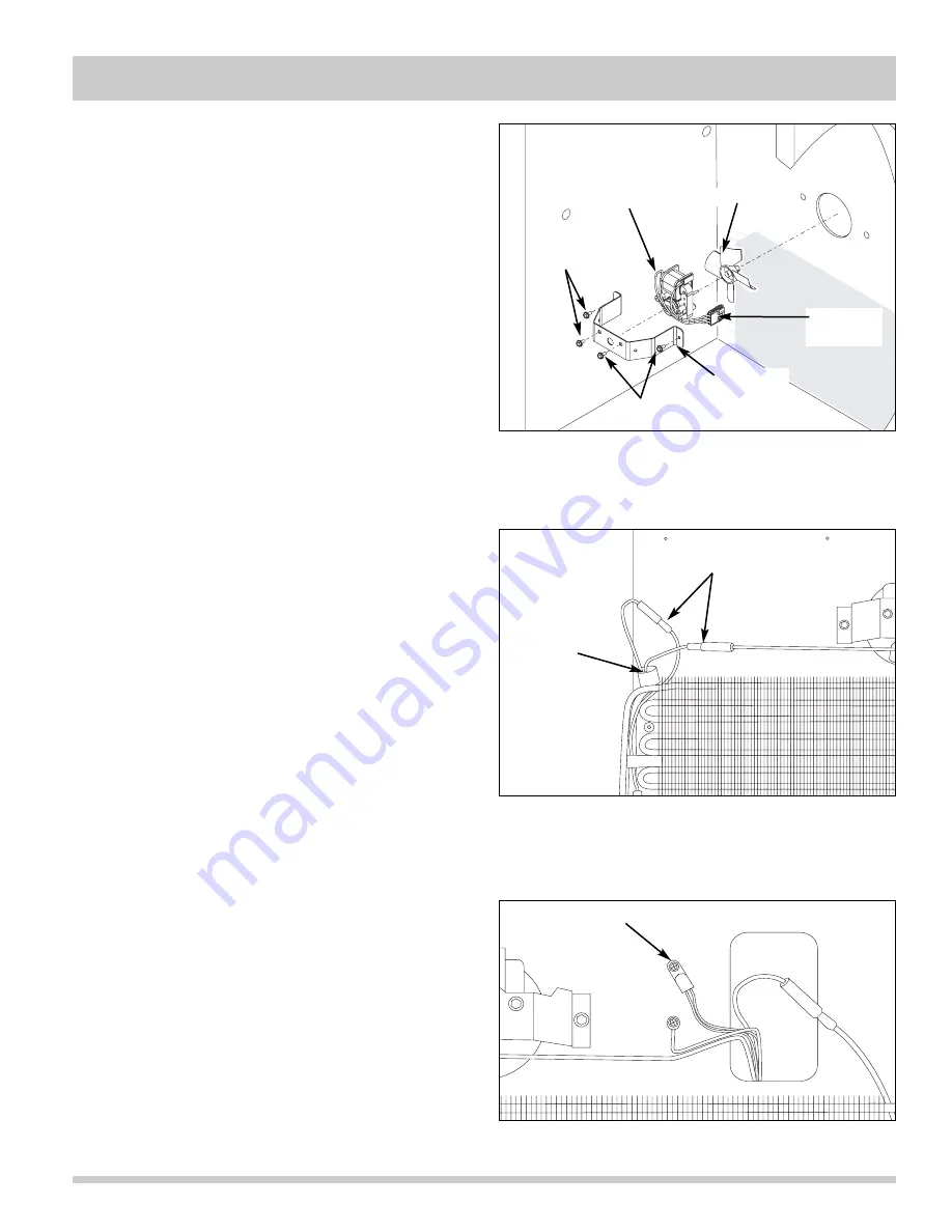
Figure 5-17. Defrost Thermostat Removal
Figure 5-18. Defrost Thermostat Removal
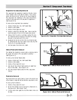
Evaporator Fan Assembly Removal
The evaporator fan assembly consists of the fan motor
mount bracket, fan motor and fan blade. Two screws
secure the fan motor to the fan motor mount bracket.
The evaporator fan assembly is then secured with two
screws to the back wall of the freezer compartment.
(See Figure 5-16)
To remove the evaporator fan assembly:
1. Remove the bottom two shelf assemblies.
2. Remove wire basket.
3. Remove the evaporator cover.
4. Remove wires from retaining clips. Disconnect the
electrical leads of fan motor at quick disconnect.
5. Using a 5/16” socket or nut driver, extract the two
hex head screws securing the fan motor mounting
bracket to the back wall of the unit.
6. Separate the fan motor from the mounting bracket
by extracting the two hex head screws securing the
fan motor to mounting bracket.
7. Pull fan blade from fan motor shaft.
Defrost Thermostat Removal
The defrost thermostat is secured with a retaining clip to
the upper left corner of the evaporator assembly.
(See Figure 5-17)
To remove the defrost thermostat:
1. Remove the bottom two shelf assemblies.
2. Remove wire basket.
3. Remove the evaporator cover.
4. Disconnect the defrost thermostat wire leads from
the wire harness. (See Figure 5-17)
5. Pull the defrost thermostat off of the evaporator
tubing.
Thermistor Removal
The thermistor is mounted with a screw to the back wall
of the freezer compartment behind the evaporator cover.
To remove the thermistor:
1. Remove the evaporator cover.
2. Extract the phillips screw securing the thermistor to
the back wall. (See Figure 5-18)
3. Cut the wires and splice the new thermistor into wire
harness.
Figure 5-16. Evaporator Fan Assembly Removal
Screws
Screws
Fan Motor
Fan Blade
Electrical
Connection
Fan Motor
Mounting
Bracket
Disconnect Here
Defrost
Thermostat
Thermistor
Содержание FFH17F8HW0
Страница 2: ......
Страница 14: ...Section 2 Installation Information 2 6 Notes ...
Страница 18: ...Section 3 Electronic Control 3 4 Notes ...
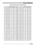
Страница 33: ...Section 4 Refrigeration 4 15 HFC 134a CFC 12 Pressure Temperature Chart ...
Страница 36: ...Section 4 Refrigeration 4 18 Notes ...
Страница 48: ...Section 5 Component Teardown 5 12 Notes ...
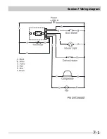
Страница 53: ...Section 7 Wiring Diagram 7 1 ...
Страница 54: ...Section 7 Wiring Diagram 7 2 Notes ...

