5
Foundation depth depends on the ground and
pier weight. Gate width is critical, so it is safer to
lay the first brick course before ordering the gate
to ensure it fits.
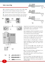
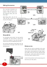
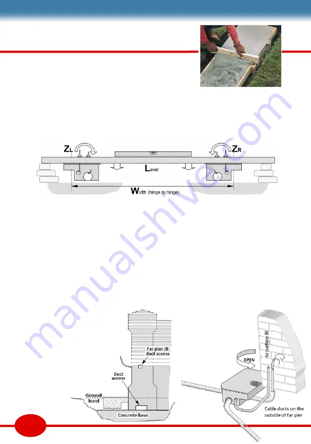
The casements can now be laid on a thin bed of
concrete over the concrete base. Fig7 shows an
alternative method where the casements are
suspended from a level bar resting on the first
few brick courses. This ensures the casements
are level and packed underneath.
Push fit ducts and drains in the casement.
Protect any exposed screw threads and tape up
any holes to prevent concrete ingress. Then
build concrete around the casement to at least
75mm, including under the pivot shelf.
Groundwork & cable ducts
Piers can be constructed hollow, infilled, or with
steel post reinforcement. That is a decision
beyond the scope of this manual.
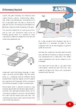
Two concrete bases are required for the piers,
set at precisely the same level. Level off 170mm
below road level to give casements a solid base,
and space for ducts and drainage to be buried.
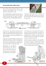
More ducts can be laid when the piers are half
height. We recommend 40mm ribbed duct for
cables and 50mm ribbed for drainage. Ducts in
the drawing below are shown terminated at the
base of the pier.
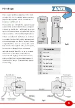
If the pier is to remain hollow, it is tidier to run
cable ducts in the pier. If solid, run the ducts up
the side of the pier (Fig 9). It is a sensible prec-
aution to run a pull cord down any long ducts. If
you have the cable, run the cable as well.
Photobeams are set 500mm
above road level. Add a 20mm
duct in each pier run to an
access hole at on the back face.
The far pier has a JB. The near
pier will have the control panel.
Fig 8
Fig 9a
Fig 9b


