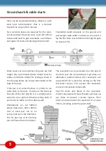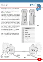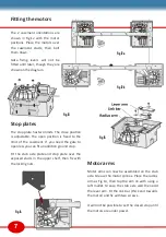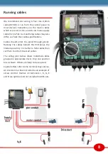
11
Further wiring plans
There are 2 safety inputs.
[F]
stops the gate
closing (Fig24).
[E]
pauses the gate in either
direction (Fig25). More safety devices may
be added as required. Refer to the safety
page for guidance on the risks.
Multiple safety contacts must be wired in a
chain (series) on the same input. Photo-
beams have a receiver [Rx] and transmitter
[Tx]. It helps if the beam direction on
[F]
is
the reverse of the beam direction on
[E]
.
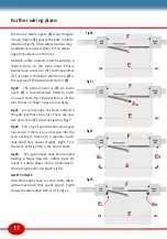
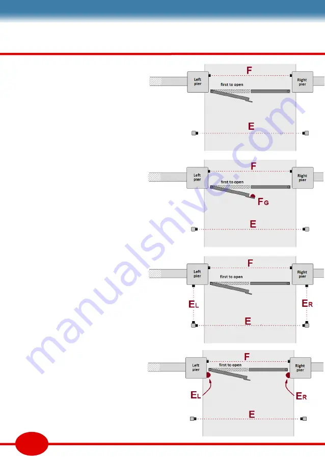
Fig20
The primary beam is
[F]
. An inside
beam
[E]
is recommended, fitted to posts
or a wall. Note the hinge position is on the
pier corner, so finger traps are less likely.
Fig21
An safety edge has been added to
the gate leaf that closes last. There are now
two devices on
[F]
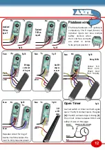
wired as Fig26 or Fig27.
Fig22
This ring of photo-beams stops gate
movement if there is any incursion into the
area enclosed. There are 2 repeater posts
that need only power (Fig29). Fig25 Tx is
the start, and Fig25 Rx is the end of chain.
Fig23
The gate hinges have been moved
making a finger trap risk. Safety input [E]
needs 2 safety edges and a photo-beam.
Wire to Fig26 (left) and Fig27 (right).
SAFETY EDGES
DRI safety edges have a 4 core cable (Blue-
yellow-black-red) that needs power. Fig30
shows the alternative DCY or DTE edges.
Fig 20
Fig 21
Fig 22
Fig 23


