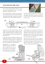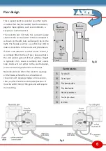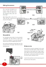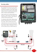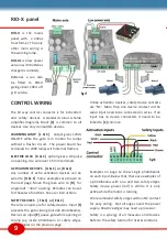
RIO-X panel
RIO-X
is the mains
panel with a 24Vac
transformer. The only
other main wiring is
the warning lamp.
RIO-XL
is a low power
version with batteries
charged is remotely.
Batteries a can also
be fitted to RIO-X
giving about 10hrs off
grid service.
CONTROL WIRING
The 10 way control connector is for ‘activation’
and ‘safety’ devices. A standard colour scheme
simplifies diagrams. Black
[C]
is common to all
devices. Use only compatible devices.
WARNING LAMP [L & C]
output gives 12Vdc
ON-OFF while the gate is in motion for lamps
without a flasher circuit. The power board has
terminals for 230V lamps with internal flashers.
ELECTRIC LOCK [K & C]
option gives a DC pulse
on opening. Use wire over 1.5mm terminals.
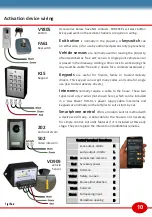
ACTIVATION DEVICES [G & C] or [D & C]
Any number of extra activation devices can be
wired to
[G & C]
. Some examples are shown on
the next page. Move the green wire to
[D]
for
single leaf “door” opening. Remotes can be set
for these two functions. See user instructions.
SAFETY DEVICES [F & C] or [E & C]
There two inputs are for safety devices. Input
[F]
prevents the gate closing (outside photobeams).
Devices on input
[E]
pause gate while opening or
closing (eg inside photobeam or safety edge).
See examples on the previous page.
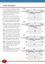
Unlike activation devices, safety device contacts
are ’NC’. More than one device contact on the
same input need to be connected in series. If an
input has no device connected, it needs to be
linked to
[C]
common.
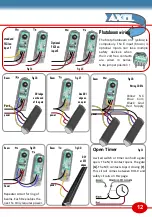
Examples on page 12 show single photobeams
on each input. Below that, there are examples of
a photobeams with one and two safety edges.
Safety device power (red) is 24Vdc. It is only
active while the motor is running.
We recommend safety edges with an NC contact
for easy wiring. Not all edges need the power
supply. Resistive edges may need a processor.
Safety is a synergy of all measures and devices.
Refer to the safety tutorial for risks & solutions.
9
Fig 17
Fig 18


