7
Fitting the motors
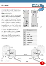
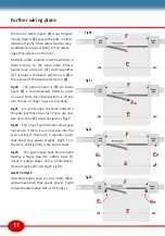
The 2 casement orientations are
shown in Fig.12 with the motor
positions. Place the motors over
the casement studs, then bolt
them down.
Gate fixing levers will not be
fitted until later, though they are
shown on the diagram.
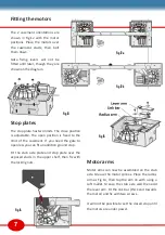
Stop plates
The stop plate has two limits. The close position
is adjustable. The open position is fixed to the
limit of the casement. If you need the gate to
open less you can fit an addition ground stop.
Fit the stub axle plate and stop plate over the
exposed studs in the upper shelf, then fix with
the locking nuts.
Fig 12b
Motor arms
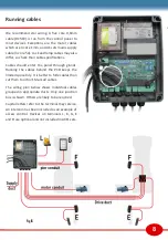
Motor arms can now be assembled on the stub
axle. Grease the motor splines. Place the radius
arm as Fig 14, then tap the arm on with using a
soft mallet. Grease the stub axle well then add
the lever arm. Fit the link bar (thick end towards
the motor) and fix with two screws..
It will not be possible to set the closed stop until
the motors are under power.
Fig 13
Fig 14
Fig 15
Fig 12a


