10
OWNER’S MANUAL
NEUTON
™
PUMP MODULE
1)
A control panel penetration/bushing will need to
be inserted to accommodate the BAS and/or zone
sensor wiring . Installer should determine optimal
positioning per final installation orientation . The
use of a knockout punch is recommended for
penetration(s) . Install bushing .
NOTE:
Take care to keep the inside of the control
panel free of metal shavings when installing hole .
2)
Mount unit to an appropriate bracing system . The
pump module can be mounted in any position that
allows the pump shaft to be oriented horizontally
while not allowing the terminal box be oriented
in a downward position (See
Figure 3
) . See the
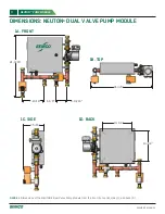
dimensional drawings in
Figures 1D and 2D
for the
dimensions between the four (4) mounting holes
for each configuration . At a minimum, 12” should
be added to the width and 8” to the depth shown
to allow reasonable service access to the pump
and the valves and to allow for a full swing of the
electrical panel door .
3)
Disconnect the o-rings that are attached to the unit
and place on each pipe connection (See
FIgure 4
) .
INSTALLATION & WIRING
RECEIVING & INSPECTION
Upon delivery, confirm that the quantity and model(s) received matches the Bill of Lading . If there is any discrepancy,
immediately notify SEMCO LLC .
Inspect the packages for signs of damage . If damage is suspected, contact SEMCO immediately . If no visible damage
is apparent, the unit should be properly stored until installation .
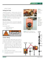
FIGURE 3.
Acceptable (A, B, E) and unacceptable (C, D) mounting orientations . Note that orientation C can be utilized provided that
the pump motor is field rotated to an acceptable position (E) .
A
B
C
D
4)
Make pipe connections . See the dimensional
drawings in
Figures 1A and 2A
for the dimensions
between pipes . All piping connection ports on
NEUTON are 1” female National Pipe Tapered
(NPT) swivel half-union adapters with face gasket
designed to connect to standard 1” male National
Pipe Tapered fittings (NFT) to be provided by the
installing contractor . Tighten the swivel nut by hand
and then gently snug with pliers (1/8 to ¼ turn) for a
leak-free joint . Do not over-tighten or you may cut
the gasket and cause a leak .
5)
WARNING!
Air in the system will damage the pump:
air must be completely eliminated from the pump
module and chilled beam loop using a vent at the
high point . The actuator control valves must be
manually opened to facilitate filling the system (See
Figure 5
) . After the system is filled, the valve should
be returned to automatic operation . Be sure the
knob has “popped” out to the engaged position to
return to automatic mode . See
Figure 6
for position
of valve knob and rotation direction switch after
E

