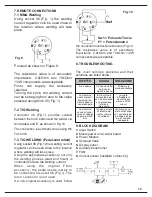
14
welding pool that has been
created.
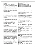
9.
To stop welding, release the torch button
(or press it again if in 4T mode) and
distance the torch from the workpiece.
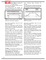
The potentiometer knob (Fig.1 – 25)
regulates the welding current.
TIG welding with HF Arc generation is very
similar to Lift-Arc welding. The only
difference is, the electrode does not need
to make contact with the workpiece. It only
needs to be app. 3-4 mm away from the
workpiece while the torch button is being
pressed to generate an arc before contact
is made.
6.2.6 Welding Parameter Setting
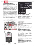
This description often refers to Figure 1.
Set the welding current turning knob 25.
The value selected will be displayed on
panel 13. App. 1 minute after being
adjusted, the new value is memorised for
future operations.
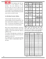
Many other welding parameters can also be
adjusted. Press button 14 (“Set”) until the
LED relating to the required parameter
lights up (LEDs 3 to 10).
The value of that parameter (or feature) can
be adjusted used knob 25 (the value will be
displayed on panel 13).
The adjustments are memorised pressing
button 14 (“Set”) or automatically in app. 1.5
seconds.
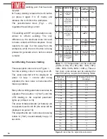
Note 1:
12 frequencies can be selected
(0.3Hz, 0.5Hz, 1Hz, 3Hz, 5Hz, 10Hz, 15Hz,
20Hz, 30Hz, 50Hz, 80Hz, 100Hz.) Three or
four duty cycle values can be selected for
each frequency, as per the following Table.
LED Name
Pre
gas
Is
Su
Pulse
I2
Sd
If
Post
gas
Pre-Gas Phase
(Gas flow before
welding)
Initial Current
(Current when
torch button is
pressed and back-
ground current)
Slop-UP Time
(Time between ls
current value and l2
current value)
Frequency and
Pulsed Duty Cycle
(Pulsation
frequency)
Welding current
Slop-Down Time
(Time between l2
current value and lf
current value)
Final Current
(Final welding
current value)
Post-Gas Phase:
(Gas flow duration
when terminating
welding)
6.2.3
0 - 20s
0.5s
6.2.3
6.2.4
From 5A
to I2 value
20 A
6.2.3
0 -20 s
0,2 s
6.2.4
3 – 100Hz
(Note 2)
30Hz
6.1
6.2
6.2.3
0 – 20 s
2 s
6.2.3
6.2.4
From 5A to
I2 value
20 A
6.2.3
0 – 20 s
5 s
TT258:
5 – 255A
100A
TT305:
5 - 300
100A
DESCRIPTION Reference
Para.
Range di
variazione
Default
Setting
3
4
5
6
7
8
9
10
Selected
Frequency
Duty-Cycle
Display Panel (13)
Readings
0.3Hz
0.3Hz
0.3Hz
0.3Hz
0.5Hz
12.5%
25%
50%
75%
12.5%
25%
50%
75%
12.5%
25%
50%
75%
25%
50%
75%
25%
50%
75%
0.31
0.32
0.33
0.34
0.51
0.52
0.53
0.54
1.1
1.2
1.3
1.4
3.1
3.2
3.3
5.1
5.2
5.3
0.5Hz
0.5Hz
0.5Hz
1Hz
1Hz
1Hz
1Hz
3Hz
3Hz
3Hz
5Hz
5Hz
5Hz
Figure 8
: describes the adjustable parameters.
Содержание TT165 AC/DC
Страница 1: ...InstructionManual TT165 AC DC TT205 AC DC TT165 AC DC TT205 AC DC ...
Страница 4: ......
Страница 5: ...TT165 AC DC TT205 AC DC ...
Страница 10: ...X ...
Страница 12: ......
Страница 30: ...20 NOTE ...
Страница 32: ...Cod 910 100 333GB REV00 ...


