11
3.
Connect the earth clamp to the
workpiece.
4.
Place the electrode in the clamp.
5.
During the entire welding process
maintain a 3-4mm distance from the
welding pool that has been created. Weld
using small zig-zag movements so as to be
able to regulate the size of the weld as
desired.
6.
To stop welding, distance the electrode
from the workpiece.
WARNING:
When “Basic” electrodes are
being used, remove any residue left on the
electrode before welding. To do that, gently
tap the electrode on a metallic surface. (If
residue is left on an arc cannot be
generated).
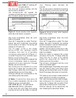
6.2 DC Welding (LED 31 and LED 22 or
23 Fig.1 ON) Select this mode pressing
button 24 repeatedly until LED22
(normal TIG welding) or LED 23 (pulsed
TIG welding) of Figure 1 lights up.
Check the Led (31 - Fig. 1) is ON.
6.2.1 Description
Argon gas welding using unmeltable tungsten
electrodes (often called TIG:Tungsten Inert
Gas welding) is a process by which heat is
generated by an arc when a non-consumable
electrode makes contact with the workpiece.
Welding occurs when the edges of the
workpiece are molted and filler metals in rod
form are used to fuse the materials together.
TIG welding can be used in all work positions
and can be applied to even very thin metal
sheets.
It is a procedure that provides easy arc control, a
powerful concentrated heat source and full control
of the amount of filler used. It is particularly useful
when accurate welding is required on a wide
range of thicknesses, when welding in awkward
positions or where deep fillings are required on
pipes, for instance. In TIG mode a variety of
materials can be welded: ferrous materials, nickel
alloys, copper, titanium, magnesium etc. It is not,
however, advisable for aluminium.
Before welding the following settings must
be programmed:
1)
Arc generation mode (Lift or HF)
2)
Welding mode (2T, 4T or 4T Bi-Level)
3)
Welding procedure (Normal or Pulsed)
6.2.2 Arc Generation Mode (Lift or
HF).
The arc can be generated either by
touching the electrode to the
workpiece (Lift mode) or by
approaching the torch to torch to the
workpiece (HF mode).
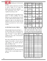
Lift generation minimises electromagnetic
disturbance and weld pool pollution.
To select Lift mode, press button 20 (Fig. 1)
repeatedly until one of the following occurs,
as appropriate :
Led 16 on:
Lift mode for 2T welding
Led 17 on:
Lift mode for 4T welding
Led 17 and 15 ON
: Lift mode for 4T Bi-
Level welding
HF Arc Generation is easy and
minimises electrode tip damage.
To set HF mode, press button 20 (Fig.1)
repeatedly until one of the following occurs,
as appropriate :
Led 18 ON:
HF arc generation for 2T
welding.
Led 19 ON
:
HF arc generation for 4T
welding.
Led 19 and 15 ON:
HF arc generation for
4T Bi-Level welding.
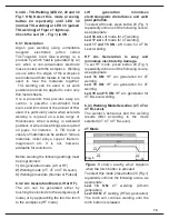
6.2.3 Welding Mode Selection (2T, 4T or
4T Bi-Level).
The welder’s behaviour and the welding
results differ according to the mode
selected (2T, 4T or 4T Bi-Level).
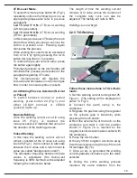
2T Mode
To select this mode press button 20 (Fig.1)
repeatedly until one the following occurs, as
appropriate:
Led 16 ON:
2T welding (Lift-Arc
generation).
Содержание TT165 AC/DC
Страница 1: ...InstructionManual TT165 AC DC TT205 AC DC TT165 AC DC TT205 AC DC ...
Страница 4: ......
Страница 5: ...TT165 AC DC TT205 AC DC ...
Страница 10: ...X ...
Страница 12: ......
Страница 30: ...20 NOTE ...
Страница 32: ...Cod 910 100 333GB REV00 ...

