9
require a three-wire cable (2 phases and
earth) with a minimum cross section area
equal to 2.5 mm².
4. OUTPUT CONNECTIONS
The welding cables are connected using
fast-connector plugs.
4.1 MMA Welding connections
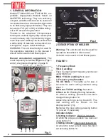
1)
Connect the electrode clamp to the
special socket on the front panel of the unit
(Fig 1 – 35). Lining up the peg and the
groove, insert the plug and screw it in well
clockwise. Do not over-tighten.
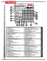
Check the direct polarity Led (Fig. 1 - 30) is
ON.
2)
Connect the earth cable to the special
socket on the front panel of the unit (Fig 1 –
38) Lining up the peg and the groove, insert
the plug and screw it in well clockwise. Do
not over-tighten.
WARNING
: Some electrodes require
negative polarity on the electrode clamp
and positive polarity on the earth cable. In
that case, invert polarity using the Fig. 1 -
35 button. Always check the electrode
packaging for instructions regarding the
required polarities!
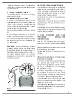
4.2 TIG WELDING CONNECTIONS
1)
Connect the earth cable to the special
socket on the front panel of the unit (Fig. 1
– 38). Lining up the peg and the groove,
insert the plug and screw it in well
clockwise. Do not over-tighten.
2)
Connect the torch to the appropriate
socket (Fig 1 – 35).
Lining up the peg and the groove, insert the
plug and screw it in well clockwise. Do not
over-tighten.
Connect the torch remote signal connector
to socket 36 (Fig.1) on the front panel of the
unit. Do not over-tighten.
5. GAS CYLINDER AND GAS
PRESSURE
REGULATOR
CONNECTIONS
Only for TIG Welding: Skip this charter
entirely if the welder is to be used for MMA.
Before connecting the gas cylinder, check
it contains pure Argon gas.
Always use welding torches with control
buttons.
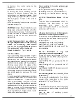
While referring to Figure 3, follow these
instructions carefully:
1.
Connect the pressure regulator (2) to the
gas cylinder (3). Tighten the bolt (6)
between the regulator (2) and the cylinder
(3). Do not overtighten to avoid damaging
the cylinder valve (1).
2.
Connect the gas hose of the torch (4) to
the pressare regulator (2) and clamp
securely using a clasp (5). (Alternatively
use cylinder and hose fast connectors).
3.
Connect the other end of the gas hose
(6) to the socket on the rear panel of the
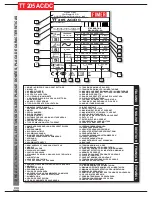
welder unit (Fig.2 – 42).
4.
Connect the gas hose from the torch to
the appropriate socket (7) on the front panel
of the unit (37 di fig 1).
4
3
2
1
6
2
5
1
3
Fig.3
Содержание TT165 AC/DC
Страница 1: ...InstructionManual TT165 AC DC TT205 AC DC TT165 AC DC TT205 AC DC ...
Страница 4: ......
Страница 5: ...TT165 AC DC TT205 AC DC ...
Страница 10: ...X ...
Страница 12: ......
Страница 30: ...20 NOTE ...
Страница 32: ...Cod 910 100 333GB REV00 ...

