background image

ADJUSTING THE FORWARD MOVEMENT SPEED (PRO VERSION)

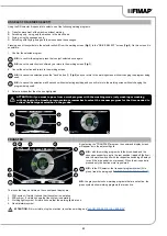
To adjust the flow of detergent solution during work, proceed as follows:

1. 

During the first few metres, check that the forward speed is adequate to the grip conditions.

2.  If the forward speed does not suit you, you can control it using the “+” and “-” buttons (1) on the 

control panel (

Fig.1

).

N.B.:

 the forward speed can be adjusted at three levels from 1 to 3. The level can be seen with 

the symbol (2) on the control display (

Fig. 2

).

N.B.:

 the machine forward speed can also be adjusted by regulating the potentiometer in the 

control panel. To do this, press the dead man's lever (2) to the required degree. The more you 

press, the higher the speed (within the limits of the level selected beforehand).

1

1

2

2

SILENT-MAX FUNCTION (PRO VERSION)

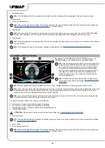
This machine has a silent-max function for reducing the noise generated by the suction motor.

To activate or deactivate this function, just press the button (1) on the instrument panel for at least three seconds 

(

Fig.1

).

N.B.:

 when the silent-max function is active, the relative LED (2) will light up on the control panel (

Fig.1

).

1

1

2

ALARM SCREEN (PRO VERSION)

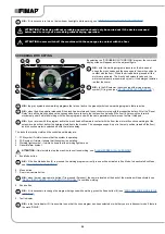
When an error occurs, the corresponding alarm screen will appear on the control display.

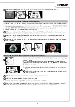
The display of the alarm consists of a first flashing line relating to the code (1) and the source of the 

error (2), while the second line displays a summary (3) of the error description (

Fig.1

). 

The alarm screen will remain visible until the error is resolved.

When an error occurs, proceed as follows:

1.  Stop the machine immediately.

2. 

If the error persists, switch off the machine, wait for at least ten seconds and switch on the machine.

3.  If the error persists contact the nearest service centre.

1

2

3

1

ALARM SCREEN (PLUS VERSION)

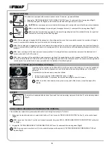
When an error occurs the symbol (1) is displayed in the information field (

Fig. 1

), it remains visible until 

the error is resolved. The “ERROR” window will also be displayed in superimposition (

Fig.2

), in it are 

described the number of the alarm, the group it belongs to and a brief description. When an error 

occurs, proceed as follows:

1.  Stop the machine and press the button (2) (

Fig.2

).

2. 

If the error persists, switch off the machine, wait for at least ten seconds and switch on the machine.

N.B.:

 to close the error screen press the button (3) (

Fig.2

).

3.  If the error persists contact the nearest service centre.

N.B.:

 the symbol (1) (

Fig.1

) remains visible until the error is resolved.

OFFICE

0000.00

100%

ECO mode

0000.00

100%

Italiano

English

Spanish

French

German

Allarme 1

Gruppo

Descrizione

Reset

?

1

2

1

2

3

4

TUTORIAL (PLUS VERSION)

The machine's internal memory contains tutorials that explain:

•  The initial commissioning of the machine (document in IT-EN-ES-FR-DE).

•  The routine maintenance to be carried out (document in IT-EN-ES-FR-DE).

•  The machine's use and maintenance manual (document in IT-EN-ES-FR-DE).

To start them, proceed as follows.

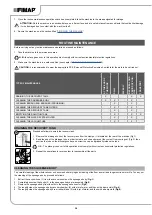
1.  With the machine on, press the menu button (1) on the working screen (

Fig.1

).

2.  Press the TUTORIAL button (2) (

Fig.2

).

34

Содержание BMg 50 Orbital

Страница 1: ...ORIGINAL INSTRUCTION DOC 10082488 Ver AB 02 2019 PROFESSIONAL SCRUBBING MACHINES USE AND MAINTENANCE MANUAL BMg...

Страница 2: ......

Страница 3: ...VE THE MACHINE 13 PREPARATION OF MACHINE 14 MACHINE SAFETY 14 INSERTING THE BATTERIES IN THE MACHINE 15 BATTERY MAINTENANCE AND DISPOSAL 15 RECHARGING THE BATTERIES 15 FILLING THE SOLUTION TANK 16 DET...

Страница 4: ...CREEN PRO VERSION 34 ALARM SCREEN PLUS VERSION 34 TUTORIAL PLUS VERSION 34 BATTERY DISCONNECT BUTTON 35 LIQUID SUCTION WAND KIT OPTIONAL 35 SPRAY GUN KIT OPTIONAL 36 OVERFLOW DEVICE 37 AT THE END OF T...

Страница 5: ...symbol Carefully read the sections preceded by this symbol meticulously following the instructions indicated for the safety of the operator and the device Danger symbol corrosive substances The operat...

Страница 6: ...display 19 Brush head extra pressure selection lever 20 Horn button 21 Optional automatic detergent dispenser kit control button FSS version or optional detergent solution recycling kit FLR version 22...

Страница 7: ...culties arise while using the machine If necessary remember that our assistance service organised in collaboration with our dealers is always available for advice or direct intervention IDENTIFICATION...

Страница 8: ...protection rating of the appliance 3 The gross weight of the appliance expressed in Kg 4 The identification code of the appliance 5 The serial number of the appliance 6 The name of the appliance 7 The...

Страница 9: ...ve pad rpm 2000 Brush head motor electrical properties 2 V W 24 500 24 500 24 680 Maximum weight exerted on brush head kg 50 60 60 Traction motor electrical properties 2 V W 24 300 24 300 24 300 Maxim...

Страница 10: ...ank to indicate the amount of water or detergent solution in the tank The symbol on the side indicates that the tank is full to about three quarters of its capacity Solution tank filling symbol Locate...

Страница 11: ...the detergent tank to indicate the capacity of the detergent tank and the dilution percentage of the FSS system Detergent solution automatic dosing system activation key label versions with FSS Used...

Страница 12: ...charge level 5 Management system symbol of the fleet connected versions with FFM 6 Forward speed level of the machine 7 Detergent solution recycling system deactivation symbol versions with FLR 8 Bru...

Страница 13: ...gaged Turn the lever 2 clockwise Fig 2 6 Drive the machine down the ramp ATTENTION during this operation check there are no people or objects near the machine 2 1 1 2 HOW TO MOVE THE MACHINE To transp...

Страница 14: ...el 6 Get off the machine 7 Press the recovery tank release lever 7 and turn the recovery tank into the maintenance position Fig 4 8 Disconnect the battery connector from the machine s main system conn...

Страница 15: ...damaged through contact with it DANGER the room used to recharge the batteries must be adequately ventilated to prevent the accumulation of gases that leak from batteries 2 Perform the procedure for...

Страница 16: ...plete disconnect the battery charger cable from the mains Disconnect the battery charger s power cable from the socket on the battery charger itself Reposition the cap 3 into the socket of the battery...

Страница 17: ...cap 5 of the detergent canister Fig 4 7 Fill the canister with the required detergent as indicated on the label of the machine CAUTION protective gloves should always be worn before handling detergent...

Страница 18: ...act with the edges or tips of metal objects 3 Stand on the left side of the machine 4 With the brush head in the up position insert the brush into the brush holder plate Rotate the brush unit the brus...

Страница 19: ...2 Check that the amount of detergent solution present in the solution tank is sufficient for the type of work to be performed If this is not the case top up the solution tank see the sections titled F...

Страница 20: ...ake sure the filter float 10 is correctly connected and is clean if not clean it see CLEANING THE RECOVERY TANK FILTERS 16 Make sure the filter strainer 11 is correctly connected and is clean Fig 12 I...

Страница 21: ...n clockwise Fig 1 4 Lower the brush head body and press the BRUSH HEAD CONTROL button 2 on the control panel Fig 2 N B as soon as the button 2 on the control panel is pressed the green LED 3 BRUSH HEA...

Страница 22: ...the traction motor brush head motor and suction motor will start working As a result the solenoid valve will also be activated and detergent solution will be dispensed onto the brushes During the firs...

Страница 23: ...washing mode only washing or washing with drying to the transfer program always remember to select the vacuum program for the time needed to collect the detergent solution on the ground DRIVE 0000 00...

Страница 24: ...mp and the traction motor are powered up N B In the DS selector the scrubbing without drying program symbol B is green read the paragraph DS DRIVE SELECT SELECTOR N B the grey symbols show working pro...

Страница 25: ...ive delay After the Reset Delay time all the squeegee support is taken to the rest position raised off the floor by pressing the forward movement pedal it will start working with the same program and...

Страница 26: ...program and with the same parameters that were set before it stopped N B if you reverse with this program active the brush head will remain in contact with the floor the motor will continue working bu...

Страница 27: ...ntre of the DS selector is the ECO MODE button pressing this will activate ECO MODE a program which guarantees the best possible performance in terms of consumption and cleaning To activate the ECO MO...

Страница 28: ...e drive pedal 5 to begin moving the machine Fig 4 N B if the button 3 Fig 2 is pressed when working in MANUAL MODE the machine will shift to ECO MODE leaving the program in use at the time active N B...

Страница 29: ...programs proceed as follows 1 From any screen press the ZONE button 1 Fig 1 2 As soon as the button 1 is pressed the ZONE SELECTION menu will be displayed Fig 2 Select one of the programs N B the name...

Страница 30: ...nages the ON OFF frequency of the buzzer is activated valid for PLUS versions Every 50ms a trigger signal is sent to the ultrasound sensor the sensor returns a signal that remains active for a period...

Страница 31: ...ed and the pressure on the brush head goes back to standard 2 3 2 3 Back 0000 00 100 POWER 0000 00 100 1 4 DETERGENT SOLUTION RECYCLING SYSTEM FLR PRO VERSIONS Upon request the machine can be fitted w...

Страница 32: ...no more any detergent solution in both tanks OFFICE 0000 00 100 ECO mode 0000 00 100 1 2 2 1 3 WORKING HEADLIGHTS PLUS VERSION The machine is equipped with front and rear working lights To start them...

Страница 33: ...ystem is not active if the symbol 2 is green the FSS system is active N B to quit the menu screen wait a short time without pressing anything or else press on any point of the display except one of th...

Страница 34: ...escription Fig 1 The alarm screen will remain visible until the error is resolved When an error occurs proceed as follows 1 Stop the machine immediately 2 If the error persists switch off the machine...

Страница 35: ...a Interventi straordinari Back 3 4 C B A OFFICE 0000 00 100 ECO mode 0000 00 100 1 2 1 2 BATTERY DISCONNECT BUTTON If any serious problems are encountered during the work operations press the emergenc...

Страница 36: ...the relative safety standards must be observed It is forbidden to use the machine in environments with a potentially explosive atmosphere 10 When the work is finished remove the kit and place it in t...

Страница 37: ...ordinary cases there is a mechanical device float under the recovery tank lid that when the recovery tank is full shuts off the air to the vacuum motor intake to protect it the sound of the suction mo...

Страница 38: ...ease the tube N B The place given over to this operation must comply with current environmental protection regulations 3 Repeat the operations in reverse order to reassemble all the parts 2 1 ROUTINE...

Страница 39: ...band Read the paragraph ASSEMBLING THE BRUSH HEAD BRUSH SINGLE BRUSH VERSION when replacing the brush 6 After checking to make sure that the brush is clean reassemble it 1 4 2 3 1 CLEANING THE BRUSH H...

Страница 40: ...ination of the bristles producing an overload on the brush motor as well as excessive vibrations 3 2 1 2 1 3 CLEANING THE RECOVERY TANK FILTERS In order to clean the filters present inside the recover...

Страница 41: ...FILTER In order to clean the water system s filter do the following 1 Close the tap s output flow and shift the knob 1 on the left hand side of the steering column Fig 1 downward 2 Remove the detergen...

Страница 42: ...ng results as well as a longer service life for the suction motor In order to replace the squeegee body s rubber blades do the following 1 Extract the vacuum hose 1 from the vacuum nozzle on the squee...

Страница 43: ...djustment of the squeegee body rubber blades guarantees better cleaning of the floor To adjust the squeegee body blades proceed as follows 1 Lower the brush head body and for PRO versions press the BR...

Страница 44: ...s the BRUSH HEAD CONTROL button 1 on the control panel Fig 1 For PLUS versions using the DS selector on the control display Fig 2 select the scrubbing with drying program 3 see DS DRIVE SELECT SELECTO...

Страница 45: ...is advisable to use softer bristles which can enter the gaps more easily Remember that when the bristles are worn and therefore too short they will become rigid and are no longer able to penetrate an...

Страница 46: ...ble is not correctly inserted into the electrical outlet Check that the battery charger power supply cable plug is connected to the mains socket The characteristics of the mains power supply do not co...

Страница 47: ...used If necessary add a small quantity of antifoam liquid to the recovery tank The floor is not very dirty Dilute the detergent more THE MACHINE DOES NOT VACUUM CORRECTLY The recovery tank is full Emp...

Страница 48: ...irective 2014 30 EC Electromagnetic compatibility directive They also comply with the following standards EN 60335 1 2012 A11 2014 EN 60335 2 72 2012 EN 12100 2010 EN 60335 2 29 2004 A2 2010 EN 61000...

Страница 49: ...ectives 2006 42 EC Machinery Directive 2014 30 EC Electromagnetic compatibility directive They also comply with the following standards EN 60335 1 2012 A11 2014 EN 60335 2 72 2012 EN 12100 2010 EN 610...

Страница 50: ...50...

Страница 51: ......

Страница 52: ...FIMAP S p A Via Invalidi del Lavoro 1 37059 S Maria di Zevio Verona Italy Tel 39 045 6060411 Fax 39 045 6060417 E mail fimap fimap com www fimap com...

Отзывы: