Hydro Logger H1
User manual
FIEDLER
electronics for ecology
9
3.2.
Mechanical design of the instrument
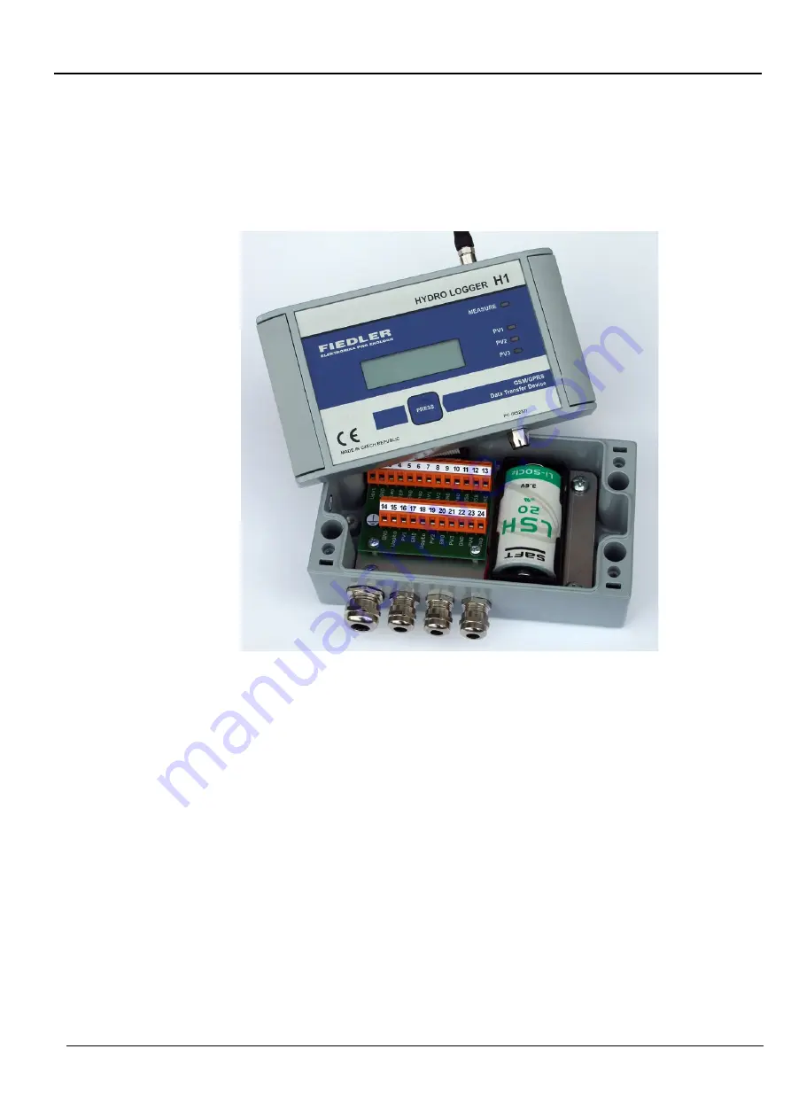
The electronic part of the Hydro Logger H1 is housed in a 160 mm x 90 mm x 60
mm metal casting, which consists of two parts. Between the two parts there is
a silicone sealing profile. The screws that connect the two parts are located on
the sides of the box under the plastic caps.
The lower part of the casting contains cable glands, a replaceable power battery
inserted in a plastic holder and a PCB connection board with connection termi-
nals and surge protectors.
The upper part of the box carries the main PCB of the device with graphic dis-
play, button and connectors for PC and GSM antenna connection. The configu-
ration switch and SIM card holder are accessible from the bottom of the lid.
There is a flat cable between the two parts. This design allows the upper top
part to be disconnected from the connection plate during installation, making it
easier to connect the cables from the sensors to the terminal block.
The high IP67-rated metal box protects the electronic circuits from external in-
terference as well as from adverse climatic conditions and is highly resistant to
mechanical damage.
As standard, the Hydro Logger H1 is equipped with 3 M12 cable glands for cables
with a diameter of 3 to 6 mm and one M16 cable gland for cables with a diame-
ter of 4 to 8 mm.
The Hydro Logger H1 can be supplied with the DH1 mounting bracket, which is
used for mounting the device on the wall. The bracket also includes 4 stainless
steel screws and a set of dowels and screws.
M e t a l b o x
C a b l e g l a n d s
M o u n t i n g b r a c k e t
Содержание H1
Страница 1: ...Small telemetry station for water applications H1 H2 Hydro Logger user manual version 1 10 ...
Страница 2: ...Hydro Logger H1 User manual 2 electronics for ecology FIEDLER ...
Страница 80: ...Hydro Logger H1 User manual 80 electronics for ecology FIEDLER Notes ...
Страница 81: ...Hydro Logger H1 User manual FIEDLER electronics for ecology 81 ...


