Hydro Logger H1
User manual
FIEDLER
electronics for ecology
55
EXAMPLE 1.: MEASURING THE LEVEL
Most commonly, the level is measured with a pressure dipping probe or an ul-
trasonic probe placed above the maximum level.
The output signal of the probes is either a 4-20 mA current output (0-20 mA, 1-
5 mA) or an RS485 serial interface. Depending on the type of output signal, se-
lect the "Measurement method" parameter and set the Input number or
address for RS485 communication.
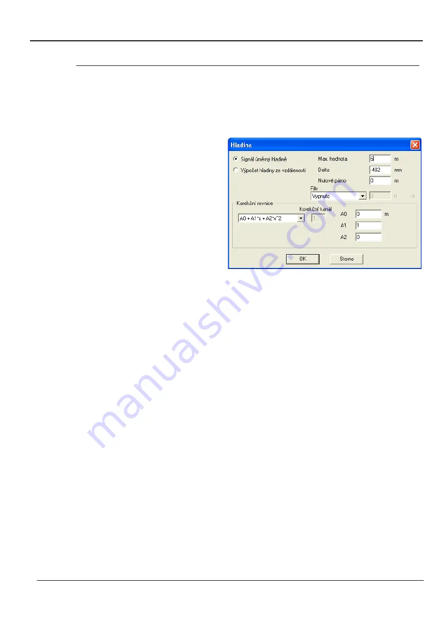
After pressing the "Ad-
vanced" button, a win-
dow opens with para-
meters that define the
measuring range, zero
offset
and
possible
correction coefficients
for calculating the level.
Use the first option "Sig-
nal proportional to le-
vel" for most probes.
You only need to set the
level vs. distance calcu-
lation for older US1000 ultrasonic probes, which sent the distance of the level
from the probe instead of the level.
This parameter is set for probes with current output, where the parameter value
corresponds to the maximum possible measuring range of the probe. Therefore,
for a pressure probe with a measuring range of 0 to 6 m of water column (corre-
sponding to an output current of 4 to 20 mA), set the parameter Max. value = 6
m.
The Max. value
parameter is set for ultrasonic probes type US1200, which send
the already measured level directly in mm.
This parameter can be used to scroll the zero level value. The additive coefficient
A
0
of the correction equation has the same meaning.
The value of the parameter determines in set units the insensitivity band in
which the signal will be artificially zeroed. In this way, various signal noises in
the vicinity of the zero value are filtered out.
Finally, the measured value can be adjusted by a 2nd order polynomial. This
option is retained for all measured quantities except flow and volume, where
the individual parameters A
0
to A
2
take on different meanings.
Filter parameters
The value of this parameter determines the maximum possible change of the
measured quantity in one second. A small value actually means a large dimming
of the signal and vice versa. A zero parameter disables signal damping.
If the measured value changes by the set limit value, the measured value will
not be stored in the memory, but the corresponding error code will be stored.
O u t p u t s i g n a l s
S i g n a l
p r o p o r t i o n a l t o
l e v e l
M a x . v a l u e
D e l t a
Z e r o b a n d
C o r r e c t i o n
e q u a t i o n
B l a c k o u t o n
E r r o r w h e n
c h a n g i n g o
Содержание H1
Страница 1: ...Small telemetry station for water applications H1 H2 Hydro Logger user manual version 1 10 ...
Страница 2: ...Hydro Logger H1 User manual 2 electronics for ecology FIEDLER ...
Страница 80: ...Hydro Logger H1 User manual 80 electronics for ecology FIEDLER Notes ...
Страница 81: ...Hydro Logger H1 User manual FIEDLER electronics for ecology 81 ...


