


Filtration Learning System
Setup
© Festo Didactic
696684
33
8.12
Electrical connection technology
8.12.1
Connection board
The connection board serves as an interface for the analog and digital input and output signals. All analog
signals are converted to 0…10 V and applied to the analog terminal. The binary signals, max. eight inputs
and eight outputs per station, are applied to the I/O terminal. This ensures compatibility with EasyPort,
SimuBox, and PLC EduTrainers.
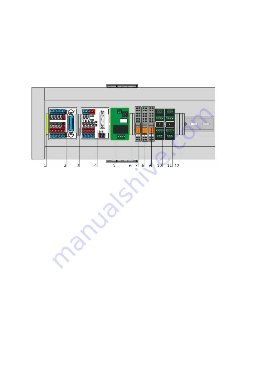
Figure 16: I/O connection board (similar to figure)
1.
Earthing terminals
2.
I/O terminal (SysLink Station): connection of the inputs, for example capacitive proximity sensors, and
connection of the outputs, for example pumps.
3.
Jumper: in the delivery state (jumper = "analog"), the
actuator (pump, heater, etc.) is controlled analogically (analog terminal UA1). By repositioning the
jumper from "analog" to "digital", the actuator (pump, heater, etc.) can also be controlled digitally.
(I/O terminal output A0.0)
4.
Analog terminal (SysLink analog): analog connection of the controlled variable x and the manipulated
variable y.
5.
Starting current limiter: limits the max. station current (e.g., starting current of pumps)
6.
Wiring terminals for end-posion sensors
7.
2-fold changeover relay for binary actuation of the motor of the pump PL2
8.
2-fold changeover relay for binary actuation of gate valve and butterfly valve, alternating
9.
2-fold changeover relay for overflow protection circuit: if a tank is overfilled, the float switch opens, the
relay drops out and interrupts the power supply to the pump motors.
10.
Motor control: analog control of the motor of pump PL1 (0...10V corresponds to 0...24V).
11.
Motor control: analog control of the motor of stirrer AG4 (0...10V corresponds to 0...24V).
12.
Wiring terminals for overflow protection circuit


