


SETTINGS
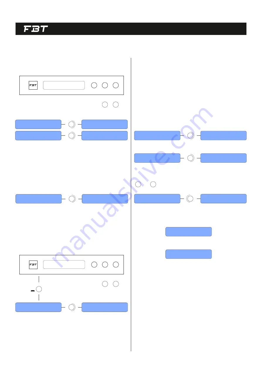
GAIN
The controllable gain range is from -18 to +12dB in 0.1dB steps.
NAVIG. / PARAM. 1
PARAM. 2
PARAM. 3
ENTER
ESC
UTILITY
DIGITAL LOUDSPEAKER MANAGEMENT
PARAM. 2
PARAM. 2
1dB step 0.1dB step
CH-A Gain
Gain = 0.0 dB
CH-A Gain
Gain = 0.0 dB
CH-A Gain
Gain = -18.0 dB
CH-A Gain
Gain = +12.0 dB
Turning
Turning
PARAM. 2
PARAM. 3
The overall polarity can be selected as normal polarity or -180° reverse
polarity, which can be used to match the phase of the loudspeaker or
correct the overall inversion caused by the wrong connec on of the signal
cable.
POLARITY
PARAM. 2
CH-1 Polarity
Polarity = Normal
CH-1 Polarity
Polarity = Inverted
Turning
DELAY
The output part provides a maximum delay of 170 milliseconds, which can
be used to align the me between the mul -way units, in a step of 10.4
microseconds / 0.01 milliseconds.
NAVIG. / PARAM. 1
PARAM. 2
PARAM. 3
ENTER
ESC
UTILITY
DIGITAL LOUDSPEAKER MANAGEMENT
PARAM. 3
1dB step 0.1db step
CH-1 Delay
Delay = 0.000ms
CH-1 Delay
Delay = 169.989ms
Turning
PARAM. 2
PARAM. 3
ENTER
PUSH
RMS COMPRESSOR
It is mainly used to limit the RMS power of the unit. It needs to cooperate
with the AES power provided by the unit manufacturer and the
amplifica on factor of the power amplifier to calculate the threshold; the
a ack me is o en determined by the period corresponding to the
frequency of the high-pass filter and the release me is always set to 16
mes the startup me.
For example, the AES power (2h) of a HF driver is 100 wa s, the impedance
is 16 Ohms, the crossover point is 1000Hz and the amplifica on factor of
the power amplifier is 40dB, then according to P=U2/R, the maximum
input voltage of the unit is 40 volts, divided by the power amplifier
magnifica on is 100 mes, the voltage limit should be ac vated when the
signal level is 0.4v, 0.4v is converted to 20log (0.4/0.775) to get -5.84 about
-6dBu, that is, the treshold is -6dBu; the cycle corresponding to the
crossover point 1000 if it is 1ms, then the start me can be set to 1ms and
the release me is 100ms.
PARAM. 2
PARAM. 2
CH-1 RMS Cmp
Enable = OFF
CH-1 RMS Cmp
Threshold = +20.0dBu
CH-1 RMS Cmp
Enable = ON
CH-1 RMS Cmp
Threshold = -6dBu
Turning
Turning
The a ack me can be adjusted from 0.1ms to 1000ms.
Compressor switch
PARAM. 2
CH-1 RMS Cmp
Atk Time = 10ms
CH-1 RMS Cmp
Atk Time = 1ms
Turning
PARAM. 2
*1ms
PARAM. 3
10ms
The start threshold can bge adjusted from -10dBu to +20dBu
CH-1 RMS Cmp
Rel Time = 100ms
CH-1 RMS Cmp
Ratio = 32:1
Release Time can be adjust from 100ms ~ 15
16


