INSTALL
For each input channel (A/B/C/D) is a female XLR connector. Even channel
numbers are for analogue inputs only.
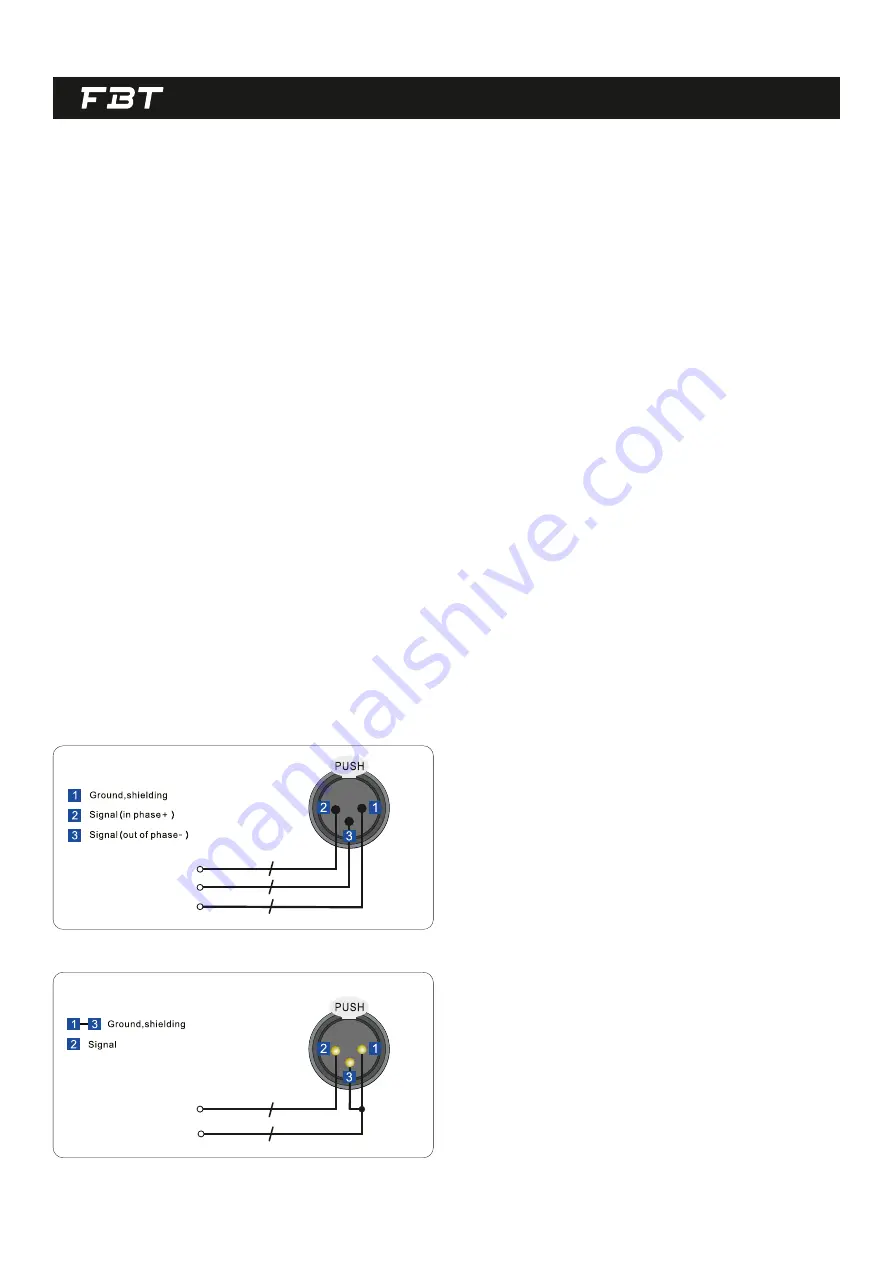
Analog signal input:
The HOT, "+" or "in phase" connec on should be made to pin 2 of the XLR
connector.
Pin 1 of the XLR connector is internally connected to the chassis.
The AC voltage provided by the audio processor with built-in global voltage
opera on must be within ±10% of the specified line voltage (90/240V~). The
third pin (grounding pin) on the power cord that comes with the package is a
necessary safety component; please do not try to disable the ground
connec on by using an adapter or other methods.
AC POWER INPUT
SIGNAL INPUT AND OUTPUT
Like all digital signal processing equipment, the signal level supplied to the
unit must be appropriate to avoid working in a low signal-to-noise ra o or
distor on. The DLM series processors can accept up to +20dBu analog signal
level, which is greater than the linear output level of most mixers, so the
impact of this type of problem is reduced. When performing equaliza on
processing, pay a en on to the boosted gain value not to be too large, so as
to avoid the gain of the unit from causing digital clipping (of course, you can
use the built-in an -clipping func on to prevent this event from happening).
It must be noted that the maximum input level in the specifica on is a clipping
level, not a safe prac cal level. It must be ensured that the clipping level is not
lower than the next device in the signal chain and a certain margin must be
le during use.
The COLD, "-" or "out of phase" connec on should be made to pin 3 of the
XLR connector.
INPUT XLR BALANCED CONNECTION
INPUT XLR UNBALANCED CONNECTION
4


