16
WORKSHOP MANUAL
TL 250
CHAPTER 5
BODYWORK
REMOVAL
A
B
C
D
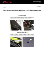
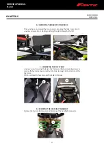
5.1 REMOVING THE SEAT
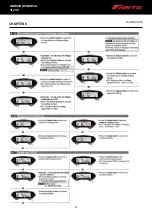
Remove the fastening screw (A) pictured and remove the seat by sliding it
backwards to release it from the hook on the tank and the bracket (B).
5.2 REMOVING THE REAR FENDER
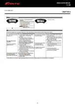
Once you have removed the seat as described in section 5.1 "Removing the seat",
unscrew the three fastening screws, two of which are on the left and right side of
the bike (marked C in the photo), and the central one D located under the seat.
To provide access to certain areas of the vehicle for inspection and work, you need to remove the relevant parts as follows:
Содержание TL 250
Страница 1: ...1 WORKSHOP MANUAL E N...
Страница 3: ...WORKSHOP MANUAL TL 250...
Страница 11: ...11 WORKSHOP MANUAL TL 250...
Страница 30: ...30 WORKSHOP MANUAL TL 250 CHAPTER 6 DASHBOARD 39 GENERAL CONTENT AND CONSULTATION ENGLISH...
Страница 49: ...49 49 WORKSHOP MANUAL TL 250...
Страница 50: ...50 50 CHAPTER 15 ELECTRICAL DEVICES 15 3 WIRING DIAGRAM TL 250 4 STROKE 2016 WORKSHOP MANUAL TL 250...
Страница 51: ...51 CHAPTER 15 ELECTRICAL DEVICES 51 WORKSHOP MANUAL TL 250...
Страница 136: ...136 136 WORKSHOP MANUAL TL 250...

