background image

21


7.3.1 Filter Oil into Receptacle (Oil Bucket) as 7.2 Above 

Warning


Removal of fryer oil must be carried out under controlled  circumstances. Refer to Health and Safety, Manhandling 

and Local Dispensing of Oil regulations.


7.3.2 Manual Removal of Oil from Receptacle (Oil Bucket)


1. Slide  receptacle  forward, and remove strainer basket and microfilter.


Note:

  The oil container may be heavy. Drain small  amounts at a time if necessary, before lifting container.  Manual 

handling regulations should be observed. 

This practice should be carried out when oil is lukewarm. 


Weight of Empty oil  filter 

– 4.25kg 

Each litre of oil 

– approx 1kg. 


2. Using handles provided, lift receptacle clear by pulling  up and forward.


Note


Care should be taken not to pull runner cradle out during  this operation. Be careful also, not to spill oil.


3. Lift   o i l   c o n t a i n e r    and   dispense   according   to   local  regulations.


4. Replace strainer basket and microfilter.


5. Replace oil container in reverse order.


Note


Cleaning of filters and oil container should be carried out on a regular basis as required. 


7.3.3 Using Oil Decanting Hose


(Refer to Figure 5)


Warning


The  decanting  hose  must  ONLY  be  used  to  decant  oil  from  unit  o il  co nt ain er   to  recommended  disposal 

vessel.  Always  wear  the  recommended  Personal  Protective  Equipment 

(PPE) 

to  prevent  injury  as  the  hose 

and  components will be HOT. 

DANGER


NEVER operate decanting hose for purposes other than  recommended.


With pump OFF and fry pot empty:


a)  Disconnect  oil  return  pipe  from  flue  quick-release  connection.


b)  Connect  decanting  hose  to  flue  quick-release  connection and connect oil return pipe to other end of  hose.


c) Using handle, point hose into disposal vessel.


d) Press filtration pump switch to switch pump on.


e) When oil has decanted, press filtration pump switch to  switch pump off.


f)  When  cooled  to  touch  temperature,  disconnect  d e c a n t i n g  hose from flue quick-release and oil return pipe.


g)  Reconnect oil return pipe to quick release connection.


Содержание G2844F

Страница 1: ...d be left with the Engineer in Charge for reference during servicing Further to this the user instructions should be handed over to the user having had a demonstration of the operation and cleaning of...

Страница 2: ...clearly caused by misuse Where an engineer finds no fault with a product that has been reported faulty Re setting or adjustment of thermostats when unit is operating to specification Cleaning and unb...

Страница 3: ...detailed below Fixing holes are provided in the fryer base to accommodate the bracket The bracket should be fitted as detailed in Figure 1 The retaining chain has a quick release eyelet Secure to fixi...

Страница 4: ...lve must be located close to the appliance to facilitate shut down during an emergency or routine servicing The cock must be easily accessible to the user The installation must be tested for gas tight...

Страница 5: ...of mains electrics integral pipe work should be checked for gas tightness using an appropriate gas leak detector Caution Installation engineers should note that for first time connection of appliance...

Страница 6: ...r Keys 1 4 Used to start cancel pre set cook times Buttons 1 4 also used to change times or temperatures when in either set mode See Section 6 5 Heat demand LED indicator This indicator will illuminat...

Страница 7: ...trols 2 4 3 G2844F G2845F Additional Controls See Figure 4 The following additional controls are located behind cabinet door 1 Burner and Temperature Controls ON OFF Switch Cuts power to burner and te...

Страница 8: ...ill also stop the flow of gas to burner To re set temperature limit thermostat refer to Figure 4 G2844F and G2845F Models 1 Turn burner and temperature controls ON OFF switch to OFF position 2 Allow o...

Страница 9: ...nents replaced MUST be fully checked after fitting to ensure safe operation e A full pre commissioning check as detailed in Section 2 5 should be carried out 3 4 PREMIX FAN Preset venturi must not be...

Страница 10: ...panel to access drain valve f Undo drain pipe and using appropriate size of spanner remove drain valve g Replace in reverse order and check for oil leak 3 11 FILTRATION PUMP When Fitted a Remove back...

Страница 11: ...data plate located inside the fryer door on LH leg support face Burner reset switch G2844 5 Control knob G2845 Drain valve G2844 5 Filter bag G2844 5 Fan speed board G2845 Fuse anti surge 5A G2844 5 F...

Страница 12: ...ransformer Solution Replace transformer and or controller PROBLEM No sound Cause Inoperable speaker Solution Replace controller PROBLEM Button Cause Inoperable key Solution Replace controller PROBLEM...

Страница 13: ...d oil to overflow into the oil bucket Action 3 The pipework has become blocked refer to Action 2 or has been inserted incorrectly into one of the quick release connections Action 4 The oil is too hot...

Страница 14: ...CRITICAL DIMENSIONS 90mm 1mm 102 5mm Phial pushed against end of guard Safety Thermostat 32mm 1mm from boss Operating Thermostat Probe Set to 0 8 Set to 10 minutes Oil Pump Timer Settings Set to F Set...

Страница 15: ...OT TO BE ADJUSTED BY THE USER The fryers are of single pan type and the following units are covered by this manual G2845F Manual control model with built in filtration G 2844F Four product key electro...

Страница 16: ...nd dried Discolouration of heated parts is caused by factory testing to ensure unit is satisfactory It will not affect quality or performance All Models A neon indicator is incorporated to indicate fl...

Страница 17: ...l service engineer Warning Do not select any setting other than FMC when using solid fats as this will trip safety thermostat or in the worst case scenario ignite liquefied oils 6 2 1 2 G2844F model o...

Страница 18: ...e shortest time remaining key is displayed and only the LED above key flashes the other s remain constantly lit Once shortest time programme ends and is accepted next shortest is displayed and LED abo...

Страница 19: ...he display will alternate between ti z and X XX where z is the number of the key pressed and X XX is the set time in minutes and seconds c Adjust the time up or down using the DOWN key 1 and the UP ke...

Страница 20: ...slide oil bucket back on to runner cradle and back into fryer Please Note Warning Do not handle filter components or adjacent surfaces when pump is operating Components will remain hot for a period af...

Страница 21: ...Replace strainer basket and microfilter 5 Replace oil container in reverse order Note Cleaning of filters and oil container should be carried out on a regular basis as required 7 3 3 Using Oil Decant...

Страница 22: ...rning The fryer is supplied with castors at rear and should be connected to supply piping by means of a connector for moveable appliances An anti tipping restraint can be attached to unit and if so th...

Страница 23: ...To relight refer to Section 6 2 Warning Ensure that all fitments are thoroughly dry and clear of water before returning to appliance No water should be allowed to mix with the oil SECTION 9 PREPARATI...

Страница 24: ...over wet food items NEVER leave a working appliance unattended SECTION 10 COOKING HINTS Frying food involves many variables and the following information is a guide only 1 Ensure frying medium is clea...

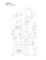
Страница 25: ...25 SECTION 11 G2844F CIRCUIT DIAGRAM...

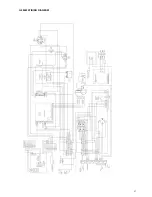
Страница 26: ...G2845F CIRCUIT DIAGRAM...

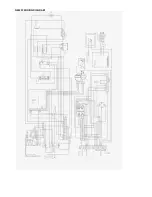
Страница 27: ...27 G2844F WIRING DIAGRAM...

Страница 28: ...G2845F WIRING DIAGRAM...

Отзывы: