40
agility
TM
Series Soft Start User Manual
MAN-AGY-001. Version 04. 21/09/2018
Modbus Communications Configuration
The Modbus communication settings may be configured from the Device menu:
•
Device >> Networks >> Modbus Network Settings >> Address (1
–
32)
•
Device >> Networks >> Modbus Network Settings >> Baud (9600
–
115200)
•
Device >> Networks >> Modbus Network Settings >> Parity (Odd / Even)
•
(Data bits = 8, Stop bits = 1)
The communication parameters should be set before connecting the Modbus master.
Transmission Modes
ASCII and RTU transmission modes are defined in the Modbus protocol specification. agility
TM
uses
only the
RTU mode
for the message transmission.
Message Structure For RTU Mode
The Modbus RTU structure uses a master-slave system for message exchange. In the case of the
agility
TM
system, it allows up to 32 slaves, and one master. Every message begins with the master
making a request to a slave, which responds to the master in a defined structure. In both messages
(request and answer), the used structure is the same:
•
Address, Function Code, Data and CRC.
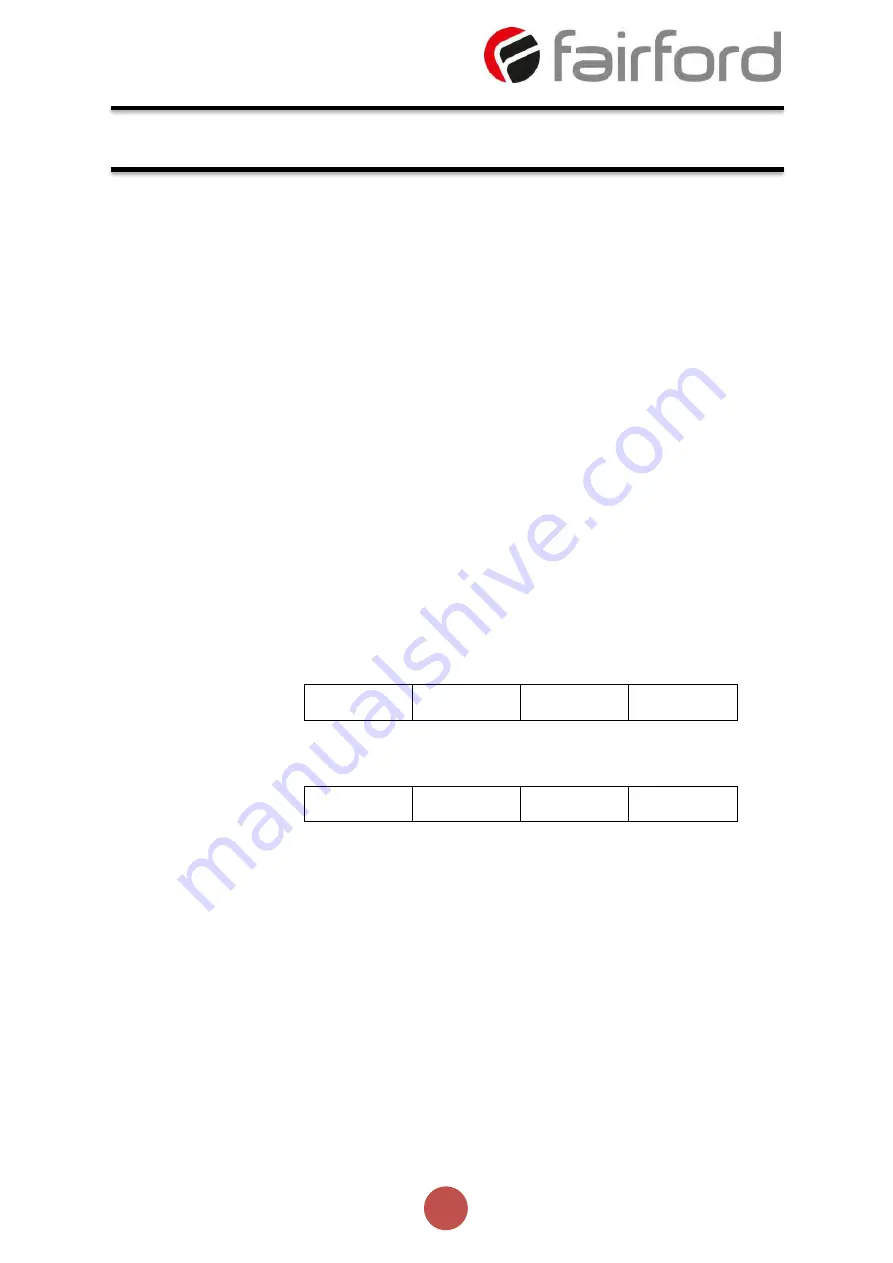
Master (request message):
Address
(1 byte)
Function
(1 byte)
Request Data (n
bytes)
CRC
(2 bytes)
Slave (response message):
Address
(1 byte)
Function
(1 byte)
Response Data
(n bytes)
CRC
(2 bytes)
Address
The master initiates the communication by sending a byte with the address of the destination slave.
When responding, the slave also initiates the message with its own address. Broadcast to address 0
(zero) is not supported.
Function Code
This field contains a single byte, where the master specifies the type of service or function requested to
the slave (reading, writing, etc.). According to the protocol, each function is used to access a specific type
of data.
Data Field
The format and contents of this field depend on the function used and the transmitted value.
Communication (continued)


