background image

EZTouchPLC

42 / 64

Index and Value Registers (Word)

The  Index  Register  data  type  is  represented   by  an   “XR”   prefix  (e.g.  XR1,  XR2 

etc.).


There  are  4  XR   memory   locations   available   in  

EZTouchPLC

.   “XR”   is   a  

Read-Write


data  type  and  it  is  mainly  used  to  point  to  the  correct  address  of  “R” 

registers. The


pointed-to “R” registers data value is stored in “#R” registers.

Value  Register  data  type  is  represented  by  a  “#R”   prefix  (e.g.  #R1,  #R2  etc.). 

There


are  4  #R  memory  locations  available  in 

EZTouchPLC

.  “#R”  is  a  Read-Write 

data type


and it is mainly used  to  read/write value of   “R”  registers  as  pointed 

out  by “XR”


registers. 

Both XR and #R registers are used in conjunction with each other and provide a


convenient way of addressing R registers.

Example:

Let's assume data values: R59=9874, R8000=32

If XR1=59

Then #R1=9874 (the actual data value of R59)

If XR2=8000

Then #R2=32 (the actual data value of R8000)

XR contains the address of the  operand  (or  specifies  a  register  that  contains  the

effective  address),  #R  is  used  to  read  or  write  the  actual  operand.  Indirect

addressing  is  often  combined  with  pre-  or  post-increment  (or  decrement)

addressing. This allows the address of the operand to be increased or decreased by

the specified  number either before or after using it. Proper usage of  XR  variables

often saves a lot of programming. 

Содержание EZTouch I/O Flex

Страница 1: ...Copyright 2015 by AVG Automation All Rights Reserved EZTouchPLC ...

Страница 2: ...Touch I O with Micro 21 Terminal Layout 21 Terminal Pinouts 22 Digital I O Specifications 24 Analog I O Specifications 26 Touch I O with Nano 28 Terminal Layout 28 Terminal Pinouts 29 I O Specifications 30 Programming the Touch I O 32 PLC Operation Sequence 32 Create a Project 34 Transfer a Project 38 CPU Memory 39 Memory Types 39 Mapping Conventions 40 Additional Features 43 Data Logging Overview...

Страница 3: ...sole property of their respective owners AVG Automation disclaims any proprietary interest in the marks and names of others Manual part number EZ TouchIO M Copyright 2015 AVG Automation All Rights Reserved No part of this document shall be copied reproduced or transmitted in any way without the prior written consent of AVG Automation AVG Automation retains the exclusive rights to all information i...

Страница 4: ...ation communication and specifications of the EZTouchPLC It also covers the troubleshooting and maintenance of an existing setup and provides understanding on how to program the panel with our EZ Editor Software Features Available in 6 8 and 10 models Built in Flash Memory 65K Colors Online Programming 2 USB Ports Type A for data logging Type B for Programming Remote Monitoring Control Built in Et...

Страница 5: ...I O Capacity 24 I O Max 40 I O Max 44 I O Max 48 I O Max 32 I O Max Expandable up to 2048 I O 64 I O Max Expandable up to 2048 I O 64 I O Max Expandable up to 2048 I O Max Power Consumption 25 Watts 24VDC 29 Watts 24VDC 29 Watts 24VDC Processors Two 32 Bit 40 MHz RISC Processors One for PLC and One for HMI Total PLC Memory 64 KB Ladder ofPLC Registers 8192 16Bit 8192 Variables PLC Typical Scan Tim...

Страница 6: ...uchPLC 6 64 External Dimensions 8 048 x 6 146 x 4 325 204 41 x 156 11 x 109 87mm 10 894 x 8 748 x 4 363 276 71 x 222 20 x 110 82mm 13 584 x10 594 x 4 299 345 x 269 1 x 10⁹ 20mm Weight 2 lbs 3 5 lbs 4 5 lbs ...

Страница 7: ...wiring section for information on connecting the Input Outputs to the EZTouchPLC terminals Step 2 Connect Power Connect the power input wires to the EZTouchPLC power terminals as outlined in the Powering the EZTouchPLC section Supply 24VDC nominal 20 28VDC power to the system Ensure the indicator LED located on the PLC base is ON green LED If not remove power from the system and check all the wiri...

Страница 8: ...all other sources of power including pneumatic and hydraulic are de energized before starting the work on a machine or process controlled by the HMI 2 Safety Circuits Most of the machines are installed with safety circuits such as limit switches emergency stop push buttons and interlocks These circuits should always be hardwired directly to the EZTouchPLC unit These devices must be wired in series...

Страница 9: ...ling the EZTouchPLC unit in areas where the following conditions may exist o Environmental temperatures above or below those specified for the EZTouchPLC unit o Prolonged exposure to humidity and liquids which may be sprayed or splashed on the equipment o Dusty environments where airborne particles may accumulate on equipment causing reduction of heat dissipation and reduction in effective electri...

Страница 10: ...lso operating at 2 5V to 5VDC logic level power supply RFI if allowed to enter the CPU inside is a killer of logic A CPU under this environment loses its brain and behaves erratically A smart industrial grade CPU like the unit s card engine when faced with RFI halts its operation instead of giving false outputs Types of RFI RFI enters electronic controls in two ways radiated RFI or conducted RFI F...

Страница 11: ... sub panels may be utilized on those electronic controls and electromechanical items that are mounted The goal is to create a medium for mounting the equipment and ensure grounding of the control s chassis to it However the door hinges and swinging panels by themselves are not enough to ensure adequate grounding Similarly the equipment enclosures are generally either painted or anodized Mounting o...

Страница 12: ...round wires from the equipment chassis terminals to the main safety ground connection o The safety ground terminal of each component can and should be connected with the shortest wire possible to the cabinet or sub panel frame o Plan the wiring routing Keep all switched power in separate ducts and if there is AC and DC power being switched keep the wiring of each branch separate from all wires and...

Страница 13: ... 4 56 115 82mm EZTouch I O Micro 8 05 204 42mm 6 15 156 11mm 4 37 110 93mm EZTouch I O Nano 8 05 204 42mm 6 15 156 11mm 4 37 110 93mm Panel Cutout Dimensions Unit Size A B Depth 6 7 46 189 48mm 5 66 143 76mm 5 37 136 40mm 8 9 25 234 50mm 7 08 179 73mm 5 53 140 46mm 10 11 91 302 41mm 8 92 226 48mm 5 56 141 22mm EZTouch I O Micro 7 46 189 48mm 5 66 143 76mm 5 37 136 40mm EZTouch I O Nano 7 46 189 48...

Страница 14: ...s below to mount the EZTouchPLC unit using DIN Clips 1 There are 4 rectangular holes in each side two at the top and two at the bottom of the chassis as shown in the following figure Choose the holes that allow the appropriate space for your mounting panel thickness 2 On each DIN Clip there are two metal tabs bent inward that fit into these holes Insert the two clip tabs into two holes top and bot...

Страница 15: ... and 10 EZTouchPLC units are stud mounted All the necessary mounting hardware is provided with the unit Use the 8 studs and 8 nuts with captive washers to secure the unit to the mounting surface Note Nuts are to be tightened with no more than 1 inch pound of torque ...

Страница 16: ...ng the Unit Connect the power input wires into the HMI s power terminals Supply 24VDC nominal 20 30VDC power to the system Ensure the indicator LED located on the PLC base is ON green LED If not remove power from the system and check all the wiring ...

Страница 17: ...S 232C cable P N EZ PGMCBL for programming the unit through a PC It serves as the default programming port on the EZTouchPLC Since COM1 has fixed communication parameters you can always connect the programming software to the PLC through the port without needing to make different configuration changes In addition this connection can be utilized to update firmware when needed ...

Страница 18: ...lable for data logging purposes Additional details about using a MicroSD Card for data logging is available in the Data Logging Overview section Push against the Micro SD card to eject it from the Touch I O unit when finished Note The Micro SD and USB flash drive cannot be used to log data simultaneously Network Option Cards Depending on model purchased a Profibus slave card or a DeviceNet slave c...

Страница 19: ...ed on the USB flash drive can be moved or copied to a remote PC by using our AVG Remote File Manager Utility Note The Micro SD and USB flash drive cannot be used to log data simultaneously RS485 Port Select models of the EZTouchPLC come with with a RS485 port available on the PLC This port allows the user to connect to a third party device as outlined above Note RS485 is currently not available fo...

Страница 20: ...own in the picture simply insert the wire and screw to tighten You can wire up to ONE 14 AWG wire TWO 18 AWG wires or FOUR 22 AWG wires in every terminal You will need a 2 5mm blade screwdriver P N EZIO SCDRV to work with the I O terminals and wiring Wires Supported UL rated at 300 volts 10 amps 14 AWG ...

Страница 21: ...EZTouchPLC 21 64 Touch I O with Micro Terminal Layout ...

Страница 22: ...EZTouchPLC 22 64 Terminal Pinouts ...

Страница 23: ...EZTouchPLC 23 64 ...

Страница 24: ...al 3 ms Status Indicators Red LED for each input Commons 2 points Fuse No Fuse Wires 1 of 14 AWG 2 of 18 AWG 4 of 22 AWG Discrete Output Specifications Number of Outputs 8 Peak voltage 50 VDC Maximum Steady state Output Current 0 5A per Output 1 0 A max per module 50 C Maximum Leakage Current 100µA 50 VDC 50 C ON Voltage Drop 2 VDC 0 5A Maximum Inrush Current 0 8A for 10ms Status Indicators Red LE...

Страница 25: ...A or 300 W Rated Switching Current 10A Contact Resistance 100mΩ at 1A 6VDC Insulation Resistance 100MΩ Min at 500VDC Dielectric Strength 5000VAC at 50 60Hz for one minute between Coil Contacts 1000VAC at 50 60Hz for one minute between Contacts Operate Time Max 10ms Release Time Max 5ms Status Indicators Red LEDs Relay Output Wiring ...

Страница 26: ...EZTouchPLC 26 64 Analog I O Specifications ...

Страница 27: ...EZTouchPLC 27 64 ...

Страница 28: ...EZTouchPLC 28 64 Touch I O with Nano Terminal Layout ...

Страница 29: ...EZTouchPLC 29 64 Terminal Pinouts ...

Страница 30: ... 24VDC Maximum Input Current 4 3 mA 26 VDC Input Impedance 11 5k 12 26 VDC ON Voltage Level 12 VDC OFF Voltage Level 2 VDC Min ON Current 2mA Min OFF Current 0 2 mA OFF ON Response 2 4 ms Typical 3 ms ON to OFF Response 2 4 ms Typical 3 ms Status Indicators Red LED for each input Commons 2 points Fuse No Fuse Wires 1 of 14 AWG 2 of 18 AWG 4 of 22 AWG ...

Страница 31: ... Max Switching Power 2770 VA or 300 W Rated Switching Current 10A Contact Resistance 100mΩ at 1A 6VDC Insulation Resistance 100MΩ Min at 500VDC Dielectric Strength 1500VAC between Coil Contact for 60sec 750VAC between Contacts for 60sec Operate Time Max 10ms Release Time Max 5ms Status Indicators Red LEDs ...

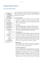
Страница 32: ...he CPU evaluates and executes each instruction in the logic program during the ladder scan cycle The rungs of a ladder program are made with instructions that define the relationship between system inputs and outputs The CPU starts scanning the first rung of the ladder program solving the instructions from left to right It continues rung by rung until it solves the last rung in the Main logic At t...

Страница 33: ...ctly written to the image table and Outputs are updated accordingly Subroutines The CPU executes subroutines when called for in the ladder program These subroutines are useful in performing the same logic operation time and time again just upon one call so you do not have to repeat the rung logic over and over again ...

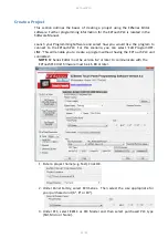
Страница 34: ...chPLC For this scenario you can select Edit Program OFF LINE This will enable you to create a program without having the EZTouchPLC unit connected NOTE EZ Series Editor must be version 6 2 or later to communicate with the EZTouchPLC Unit firmware must be k 5 80 or later 1 Enter a project name e g Test Click OK 2 Under Panel Family select EZ3 Series Then select the size appropriate for your purchas...

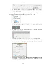
Страница 35: ...ocated on the right side of the programming screen Click on NO Contact 2 Click on the main ladder logic programming window to place the instruction as shown in the image below 3 Then double click on the icon and enter the tag name as Start Click OK 4 A new dialog box will appear asking for the PLC address memory location Enter S1 in the field to the right of Address String The Data Type should be ...

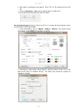
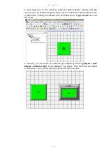
Страница 36: ...shed Create a Panel Program Click on Panel and Scr 1 to create the Panel display screen as explained in the sample below 1 In the Main Menu click on Objects Buttons Buttons The screen below will appear Enter START for Tag Name Click OK 2 A dialog box might appear requesting the memory location Enter S1 in the field to the right of Address String The Data Type should be marked as DISCRETE Click OK ...

Страница 37: ...d to adjust the object s appearance or attributes Clicking Simulates Press will allow you to toggle between On and Off states 4 Similarly you can create an Indicator Light Object by selecting Objects Data Display Indicator Light Enter Lamp for Tag Name Click OK Place the object on the panel Your screen should look like the picture below ...

Страница 38: ...SB programming cable 1 Please connect your USB programming cable to the panel and your computer prior to launching the EZ Series Editor Software 2 Under Transfer To select Both in order to transfer both the created Panel program and the PLC ladder logic project 3 Select Serial COM xx as method of transfer under PC to Panel Connection And then click Start Transferring via Ethernet 1 Select Ethernet...

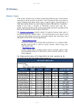
Страница 39: ...or inputs outputs control relays and timer counter bits o Word Memory Type A word memory type is a 16 bit location that is normally used to store and manipulate numeric or ASCII data A word memory location is also called a Register The following table displays all the Register Discrete types supported by the EZTouchPLC along with their address range syntax etc EZTouchPLC Memory Map SYNTAX TAAAA T ...

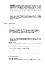
Страница 40: ...ing Conventions Discrete Inputs Outputs Discrete Inputs Discrete Inputs are denoted using an I pre fix e g I1 I4 etc The maximum number of physical Inputs available in an EZTouchPLC with Micro is 24 Hence you may only use I1 I24 in your main logic Maximum number of physical Inputs available in an EZTouchPLC with Nano is 16 Hence you may only use I1 I16 in your main logic Discrete inputs are Read o...

Страница 41: ... real physical device like a switch output coil etc They are only internal to the CPU You cannot program discrete internals as discrete inputs or discrete outputs for the physical inputs or outputs Note In this example memory location S1 will be powered when input I1 turns on you can then use a discrete internal as an input in another rung Register Internals Word Internal Registers are denoted usi...

Страница 42: ...R registers as pointed out by XR registers Both XR and R registers are used in conjunction with each other and provide a convenient way of addressing R registers Example Let s assume data values R59 9874 R8000 32 If XR1 59 Then R1 9874 the actual data value of R59 If XR2 8000 Then R2 32 the actual data value of R8000 XR contains the address of the operand or specifies a register that contains the ...

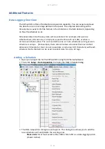
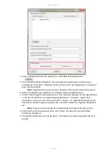
Страница 43: ...certain event takes place The user can define one or more schedules as long as each schedule is unique For example there cannot be two schedules that each collect data every 30 seconds User can also associate a name up to 8 characters with each schedule Each schedule can be used to collect data for up to 32 tags Adding a Schedule 1 Open your project file for the EZTouchPLC using the EZ Series Soft...

Страница 44: ...ed below 7 Under Select Tags for Data Acquisition the selection displays all the tags defined in the panel with their corresponding tag addresses To select a tag for data acquisition click on it and then press the button To deselect the tag for data acquisition select it again and press the button Maximum tags per schedule is 32 Note Tags can also be selected or deselected by double clicking on th...

Страница 45: ...Time based at Specifc Times Allows you to store the value of a group of tags up to 10 specific times You may always edit delete a specified time 3 Event Based Allows you to create an event and store the values of a group of tags on the occurrence of the same Based on the data type of the event tag schedule can be either Discrete Event Type or Numeric Event Type Discrete Type Event ...

Страница 46: ...f the same during a set time period Based on the data type of the event tag schedule can be either Discrete Event Type or Numeric Event Type a Set how frequently the data is stored through the Time Based interval anywhere from every 1 second to every 1000 hours b Select either a Discrete Type Event or a Numeric Event Type Discrete Type Event Numeric Type event ...

Страница 47: ... for possibly reading it in a SD card reader When Panel sees this tag as set all buffered data is written to the files and files are closed for safe removal of the card Another discrete tag Safe to Eject Card is set to indicate that it is now safe to remove the SD card without fear of file corruption At the same time the Request tag is reset by the panel Safe to Eject Card Tag This is a discrete i...

Страница 48: ...ition to display the DAQ Schedule dialog 3 Select either USB Flash Drive or MicroSD card 4 Click OK and then save the project Option 2 On the EZTouch I O Flex 1 Press the upper left corner of the EZTouchPLC screen for a minimum of six seconds to access the Setup Mode 2 After selecting the appropriate language for the unit the unit will enter the Setup Mode shown below Press the LogtoSD button to c...

Страница 49: ...stribution of panel updates in the field sending field service personnel or mailing CDs OEM Projects are protected since end users cannot modify the projects The end user benefits from convenient fast and easy updates without needing to purchase the EZTouch Editor software Creating a Pack File 1 Use the EZ Series Editor Software to open the project you wish to distribute 2 Click on File Create OEM...

Страница 50: ...I O Updater application to update his her panel with the selected project s and or firmware To open a pack file follow the steps below 1 Click on the zipped OEM Package file that you have It contains EzUpdate exe Ezupdater MFC application and example pkg PKG File Extract these file in a folder of your choice 2 In this example files have been extracted in a folder named as example_OEM Package 3 Cli...

Страница 51: ...ater window appears on the screen with an option to select the communication port You may also test the connection before a final click to Update button Click on the Update button to update the Project and or the Firmware on your EZSeries TouchPLC ...

Страница 52: ...s 1 Create a USB file hmi using the EZTouch Editor 2 Save the file on the USB Flash drive only in the root directory 3 Insert the USB stick into the EZTouch I O USB port 4 The panel brings up a list of projects that are available on the USB Flash drive Select the necessary project and press OK If the panel is not compatible with the project selected an Error message is displayed 5 The project is a...

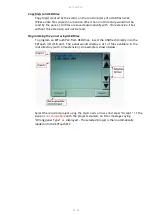
Страница 53: ...ead Programming the panel using USB Drive To program an EZTouchPLC from USB Drive insert the USB flash directly into the EZTouch I O USB port The panel would display a list of files available in the root directory with hmi extension An example is shown below Select the required project using the Up D ow n arrow s and press ccept I f the panel is not compatible with the project selected an Error me...

Страница 54: ...mote Monitoring and control we need to follow these steps 1 Use EZTouch editor to set up IP address of the panel 2 Use EZTouch editor to set up remote users and authentication level 3 Use RMC Remote Monitoring Control software to connect to the panel remotely Setting up Remote Users The EZ RMC Software can be used with or without defining authorized users If you don t define any remote users then ...

Страница 55: ...EW A user can remotely log on to the panel and monitor any of the panel screens with live data including the currently displayed screen Remote OPERATION A user can remotely log on to the panel and monitor any of the panel screens with live data including the currently displayed screen as well as can remotely touch the objects on the panel to effectively operate or control a machine plant WARNING B...

Страница 56: ... RMC software would read information from the panel A lower polling time may impact the performance of the panel Remote User Clicking OK will prompt you to provide user name and password if at least one remote user has been set up Please note that both user name and passwords are case sensitive If no remote users were defined this dialog box would not appear Access Password Projects requiring an A...

Страница 57: ...abinet Ensure that the unit is free from dust humidity and corrosive gases Error Checking Process The EZTouchPLC performs a standard diagnostic routine during each CPU scan This is called the error checking step The primary task of this step is to identify various types of CPU and I O failures We classify these errors failures broadly into two categories Fatal and Non Fatal Fatal Errors These erro...

Страница 58: ... access the battery 2 The battery is located in the upper left hand corner as shown in the figure below Remove the old battery and replace with a new 1 2 AA 3 6 V Lithium Battery Part Number EZ BAT 3 Close rear cover and ensure that the door latches 4 Reconnect power source Connect to PC and run the Programming Software to transfer back the user program to the EZTouchPLC The Real Time Clock RTC wi...

Страница 59: ... is always advised to take a backup of the project before firmware upgrade process 1 Insert the EZ PGMCBL programming cable into the COM1 port Then launch the EZ Panel Editor software 2 Select Edit Program OFFLINE and enter a project name e g Test Click OK 3 Under Panel Family select EZ3 Series Then select the size appropriate for your purchased unit 6 8 or 10 4 Under PLC select EZPLC as PLC Model...

Страница 60: ...EZTouchPLC 60 64 6 Use Browse to locate the appropriate firmware version 7 Verify Serial COM1 is selected under the PC to Panel Connection then click OK ...

Страница 61: ...t a USB cable or EZ PGMCBL programming cable Then launch the editing software EZTouch Editor 2 Select Edit Program OFFLINE and enter a project name e g Test Click OK 3 Select EZ3 under Panel Family Then select the size appropriate for your purchased unit 6 8 or 10 4 Under PLC select EZPLC as PLC Model and then select purchased PLC type Std Micro or Nano 5 Click OK to launch the editing software pr...

Страница 62: ...EZTouchPLC 62 64 8 Once the dialog box appears select Configure Ethernet Attributes Type in the necessary changes and click Set Ethernet Parameters Click OK 9 Next save the project ...

Страница 63: ...er and it has auto detect feature Issue USB Flash drive is not recognized Solution Using a different USB Flash drive ensure the USB function is enabled Using a low memory capacity USB Flash drive preferably less than 2 GB press and hold the upper left corner of the Touch screen for about 6 seconds to reach the Setup menu on the panel Click on English Check the 2 pre programmed buttons to ensure US...

Страница 64: ...sue Selected panel does not match the connected panel write to panel is aborted Solution Correct panel type When writing transferring the project to the panel the panel type selected on the screen Step 1 Project Information must match the panel that the computer and PLC are physically connected to or the program loader will not upload the project Exit the OFF LINE Editor to the Step 1 Project Info...

Отзывы: