


Model 5601MSC
Model 5601MSC Master SPG/Master Clock System
Page - 74
Revision 2.2
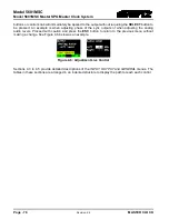
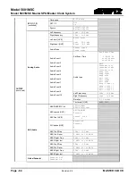
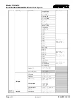
MASTER CLOCK
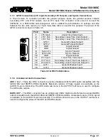
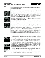
Inputs
NTSC ref with GPS
1080i ref with GPS
10MHz ref with Syncro
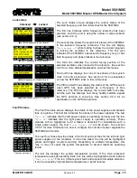
The
Inputs
status screen displays the status of the reference inputs, syncro link,
and General Purpose Inputs.
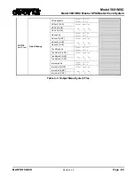
The first line displays the name of the detected video reference that is present on
the reference loop input. See section 2.2.5 for a list of valid reference types.
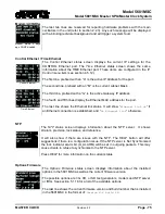
For NTSC-M and PAL-B black burst references, an approximate Subcarrier to
Horizontal (SCH) measurement of the input will be shown. If the SCH error is
greater than 35º, this line will alternate between “
(SCH>35)
” and “
H-lock
” to
indicate that the 5601MSC has fallen back to locking to horizontal sync only. If the
burst phase cannot be measured reliably, it will display “
unlockable
”.
The second line displays the detection of a 10MHz or 5MHz continuous wave
(CW) frequency on the reference loop input.
The third line displays the current status of the GPS receiver. This is the same
status that is displayed on line 5 of the
Lock Status
screen.
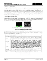
The fourth line shows the current status of the syncro link (if enabled) that is
available when two 5601MSC units are connected through a 5601ACO2. See
section 2.3.3.3 for more information on syncro.
The fifth line displays the status of the LTC/IRIG input. If LTC is present it will
show “
LTC ok IRIG n/a
”. If IRIG is present it will show “
LTC n/a IRIG ok
”
The sixth line shows the status of the General Purpose Inputs. These GPI inputs
are activated by connection to ground. The status will be “
GPI1 LO
” or “
GPI2 LO
”
when either GPI has been activated. See section 3.3 for information on the GPIs.
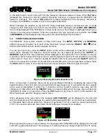
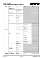
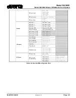
Modem/ACO2/Hw
No modem option,
SNMP read only
Modem inactive, SNMP
fully enabled, link to
5601ACO2 bank A
detected
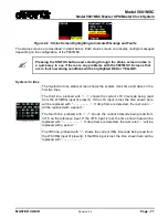
The
Modem/ACO2/hw
status screen displays various information about the
5601MSC including the modem state, SNMP status, connection to a 5601ACO2,
and also any critical hardware failure messages.
The first line displays the current status of the modem. When dialing the modem,
it is useful to view this status line to watch the progress of the synchronization.
After a successful negotiation this line will display “
Last mdm Xd h:mm
” to show
how many days, hours and minutes have elapsed since the system clock was
synchronized by the modem. If more than 10 days have elapsed, this line will be
highlighted yellow and trigger a system warning to indicate the system clock may
no longer be considered accurate. See section 2.3.3.2 for information on how
modem dial-up time synchronization works.
The second line shows the state of the SNMP, whether it has been disabled, fully
enabled (read/write), or enabled for status reporting only (read-only).
The third and fourth lines show whether connection to a 5601ACO2 has been
detected with the SNSA and SNSB lines on the AUDIO connector. This feature
can be used to enable automatic highdrive (see section 0).
Содержание 5601MSC
Страница 2: ...This page left intentionally blank ...