Model 5601MSC
Model 5601MSC Master SPG/Master Clock System
INSTALLATION
Revision 2.2
Page - 61
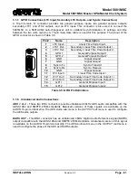
3.1.7. GPIO Connections (LTC Input, Secondary LTC Outputs, and Syncro Connections)
A 15-pin female ‘D’ connector provides two general purpose inputs, two general purpose outputs,
secondary LTC1 and LTC2 outputs, and an LTC input. This connector is also used to connect the
5601MSC to a 5601ACO2 auto-changeover unit to establish synchronization of settings and time
between the two units (syncro). A 15-pin male-male cable is used for this purpose. The pinout of the
GPIO connector is shown in Table 3-5.
Pin #
Name
Description
1
LTC Input -
Linear Time Code Input -
2
LTC1 Out -
Secondary Linear Time Code Output 1 -
3
LTC2 Out -
Secondary Linear Time Code Output 2 -
4
GPO 1
General Purpose Output 1
5
GPO 2
General Purpose Output 2
6
GND
Signal Ground
7
GND
Signal Ground
8
Syncro Tx
Syncro Transmit
9
Syncro Rx
Syncro Receive
10
GND
Signal Ground
11
LTC Input +
Linear Time Code Input +
12
LTC1 Out +
Secondary Linear Time Code Output 1 +
13
LTC2 Out +
Secondary Linear Time Code Output 2 +
14
GPI 1
General Purpose Input 1
15
GPI 2
General Purpose Input 2
Table 3-5: GPIO Pin Definitions
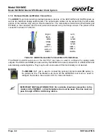
3.1.8. Unbalanced Audio Connections
AES 1 & 2 -
These two BNC connectors provide unbalanced 48kHz AES audio compatible with the
AES3-1992 and SMPTE 276M standards. Balanced versions of these signals are available on the
AUDIO 16-pin terminal strip. The
AES Audio
sub-menu in the
OUTPUT
root menu is used to configure
the AES audio outputs.
DARS OUT -
This BNC connector has an unbalanced 48kHz Digital Audio Reference signal (DARS)
output compatible with the AES3-1992 and SMPTE 276M standards. A balanced version of this signal
is available on the AUDIO 16-pin terminal strip. The
AES Audio
sub-menu in the
OUTPUT
root menu is
used to configure the phase of the AES and DARS outputs.
5
51
01
1
11
6
Содержание 5601MSC
Страница 2: ...This page left intentionally blank ...

