


Model 5601MSC
Model 5601MSC Master SPG/Master Clock System
Page - 14
Revision 2.2
OPERATION
Pulse Signals
1Hz
1/1.001Hz
6/1.001Hz
PAL Colorframe
IRIG1 Datum
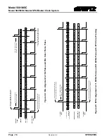
The pulse output modes provide timing pulses that can be used to lock downstream
equipment or can be helpful for troubleshooting purposes. These outputs cannot be
phased and always remain phase-locked to the frequency reference. These signals
may not be affected by any global phase offset (refer to Table 2-1).
The pulse type is set with the
Pulse type
menu item (see section 4.4.2.2.12). Refer
to the pulse diagrams in Figure 2-2 and Figure 2-3 for timing relationships.
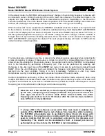
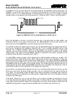
The 1Hz pulse goes high at the beginning of each second (see Figure 2-4).
The 1/1.001Hz pulse indicates the start of the second for 29.97Hz LTC/VITC rates
and is also synchronized to NTSC color field 1 (see Figure 2-5). Will be high for the
duration of NTSC color field 1.
The 6/1.001Hz pulse indicates where 59.94Hz video coincides with the 23.98Hz
standards. This pulse is only phase locked when using a GPS reference or NTSC
with a ten-field pulse (see Figure 2-5).
The PAL Colorframe pulse will be high during PAL color field 1. It will only be phase
locked when referenced to GPS or a PAL-B reference (see Figure 2-4).
The IRIG1 Datum pulse will go high at the start of the IRIG second for 100ms. This
pulse will be aligned within 20 microseconds of the GPS 1PPS pulse when locked to
a GPS reference.
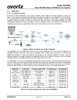
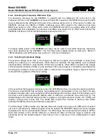
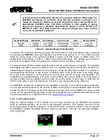
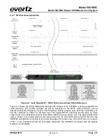
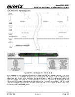
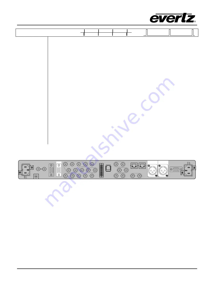
2.1.2. Timecode Outputs (LTC & IRIG)
GPIO
LTC / IRIG
OUTPUT 1
LTC / IRIG
OUTPUT 2
There are two LTC/IRIG outputs, each with primary outputs on XLR connectors and secondary copies
available on the GPIO DB15 connector. The LTC outputs are driven by the master oscillator and will be
locked in frequency and phase to the selected reference. The LTC1 and LTC2 outputs are generated
independently from one another and can be configured to run at different rates. Refer to section 2.1.2,
which describes the operation of the 5601MSC with regards to LTC and IRIG timecode.
The LTC1 primary output on the XLR connector has an LTC power driver which can be enabled
through the menu system or remotely through SNMP. Once enabled, it su12V power on pin 3 of
the XLR for powering downstream Evertz clocks. See section 3.1.4 for wiring information.
If the IRIG option is installed, either of the LTC outputs can be switched to IRIG mode to supply IRIG-B
timecode. There are several different IRIG-B formats available (see section 2.3.5).
Содержание 5601MSC
Страница 2: ...This page left intentionally blank ...