background image

ESP-200

Plasmarc Cutting System

Instruction Manual

F15-462-C 

02 / 2008

Содержание ESP-200

Страница 1: ...ESP 200 Plasmarc Cutting System Instruction Manual F15 462 C 02 2008 ...

Страница 2: ...le responsibility for any malfunction which results from improper use faulty maintenance damage improper repair or alteration by anyone other than the manufacturer or a ser vice facility designated by the manufacturer Be sure this information reaches the operator You can get extra copies through your supplier These INSTRUCTIONS are for experienced operators If you are not fully familiar with the p...

Страница 3: ...SECTION 1 SAFETY 5 SECTION 2 DESCRIPTION 7 SECTION 3 INSTALLATION 11 SECTION 4 OPERATION 23 SECTION 5 cutting quality 61 SECTION 6 Maintenance 67 SECTION 7 troubleshooting 73 SECTION 8 Replacement Parts 83 table of contents ...

Страница 4: ...d in force within the EEA has been used in the design Följande harmoniserande standarder har använts i konstruktionen EN 60974 1 Arc welding equipment Part 1 Welding power sources EN 60974 10 Arc welding equipment Part 10 Electromagnetic compatibility EMC requirements Additional information Tilläggsinformation Restrictive use Class A equipment intended for use in locations other than residential B...

Страница 5: ...plasma cutting equipment must be familiar with its operation location of emergency stops its function relevant safety precautions welding and or plasma cutting 2 The operator must ensure that no unauthorized person stationed within the working area of the equipment when it is started up no one is unprotected when the arc is struck 3 The workplace must be suitable for the purpose be free from draft...

Страница 6: ...n the event of malfunction PROTECT YOURSELF AND OTHERS WARNING Read and understand the instruction manual before installing or operating CAUTION Class A equipment is not intended for use in residential locations where the electrical power is provided by the public low voltage supply system There may be potential difficulties in ensuring electromagnic compatibility of class A equipment in those loc...

Страница 7: ...d cutting applications It can be used with other ESAB products such as the PT 26 and PT 600 torches an optional plumbing box and a remote set up pendant 50 to 200 Amperes cutting current range Forced air cooled Solid state DC power Integral water cooler Input voltage protection Local or remote front panel control Thermal switch protection for main transformer and power semiconductor components LED...

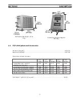
Страница 8: ...l Use of torches not designed for this console could result in a hazardous electric shock Use only torches designed for the ESP 200 Console WARNING 2 3 Dimensions and Weight 22 in 550mm 42 in 1050mm 44 in 1100mm ESP 200 Console Weight 725 lbs 330kg ...

Страница 9: ...Hoses and Cables for options 25 ft 7 6m 50 ft 15 2m 75 ft 22 8m 100 ft 30 4m 150 ft 45 7m Cooling Water Hoses console to plumbing box 2 required 33132 33133 33134 33135 33136 Control Cable plumbing box to console 22264 22265 22266 22267 22268 Pilot Arc Lead plumbing box to console 33303 33304 33305 33306 33307 Power Lead console to plumbing box 22001 22002 22003 22004 22005 Pendant Control Cable 3...

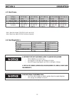
Страница 10: ...der separately Note 2 Requires adapter P N 74S76 order separately section 2 description 2 6 Gas Regulators Station Regulator Cylinder Regulator Nitrogen 19155 998343 Oxygen 998961 998336 Argon Hydrogen H 35 998341 Air 30338 N A A separate start gas regulator is always required For air plasma use air start gas For oxygen or nitrogen use nitrogen start gas For H 35 argon hydrogen use H 35 or nitroge...

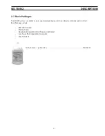
Страница 11: ...lable as a pre engineered package or can be ordered as individual parts as listed Basic Packages include ESP 200 Console Plasma Torch Appropriate regulators for the gases indicated Gas hoses from regulators to console Torch coolant Torch Coolant 1 gallon 3 8 L P N 156F05 ...

Страница 12: ...12 section 2 description ...

Страница 13: ...s for air obstructions Do Not Restrict Air Flow Restricting intake air with any type of filter on or around the Plasma console will result in overheating and may void the warranty caution 3 3 Placement A minimum of 2 ft clearance for cooling air flow Plan for top panel and side panels having to be removed for maintenance cleaning and inspection Locate the ESP 200 relatively close to a properly fus...

Страница 14: ...nductors in raceway or cable Local codes should be followed if they specify sizes other than those listed above Input current values given in this table are at maximum output power 40kW 200 amps at 200VDC Dedicated power line may be necessary ESP 200 is equipped with line voltage compensation but to avoid impaired performance due to an overloaded circuit a dedicated power line may be required NOTI...

Страница 15: ... ground lug provided above TB2 7 position terminal block 6 Connect three power leads of input power cable to terminals located atop the main contactor Secure the leads by tightening each screw 7 Connect jumper power cables from bottom of the main contactor to proper input voltage marked on auto transformer Unit is factory set for 575V as shown at the left 8 Connect jumper on TB2 to proper input vo...

Страница 16: ...ption Section 2 or Replacement Part Section 7 for part numbers Note Leave Oxygen Plasma Gas cap plug attached DO NOT USE OXYGEN WITH PT 26 TORCH Install filter regulators if using shop air for any of three process gases Start Shield Cut Gas Filter 5 micron Regulator 5 to 125 PSI 0 35 to 8 63 bar ESAB P N 30338 Note Refer to your torch manual for proper pressure flow settings View as shipped Start ...

Страница 17: ...oltmeter WARNING WARNING 3 5 Connecting PT 26 Plasma Hand Torch 3 5 1 PT 26 and ESP 200 Output Cables Hoses and Adapters customer supplied Hose and cable lengths vary depending on system Coolant Return pilot arc cable inside Coolant Supply plasma current cable inside Switch Lead Shield Gas Plasma Gas Work Cable SEE Description Section 2 for part numbers NOTE Do not use the PT 26M mechanized on a C...

Страница 18: ... and water fittings during assembly 1 Thread 4 torch service lines through the bushing at middle right side of front panel and proceed as follows a Insert pilot arc adapter into left hand threaded pilot arc fitting b Connect coolant return hose male left hand thread to the adapter Thread service lines through bushing Pilot arc fitting Pilot arc adapter P N 999278 c Connect pilot arc cable to one o...

Страница 19: ...ch lead Note The PT 26M requires an auxiliary pilot ON switch box Item number 1 at the left is not included in the PT 26M torch bundle See next page for details PT 26 Torch Bundle Leads 1 Switch Lead 2 Electrode Cable Coolant Supply Hose 3 Plasma Cut Gas Hose 4 Coolant Return Hose 5 Shield Gas Hose Pilot ON Switch Box Used with a PT 26 mechanized plasma torch Connect cable same as Step g from the ...

Страница 20: ...er on rear panel as viewed from the rear Note A second filter regulator can be mounted on the left 5 Connect air hose assembly P N 678152 to filter regulator outlet fitting and to the N2 Air plasma gas fitting on the rear panel Note The air hose assembly has a left hand threaded nut fitting on one end and a right hand threaded nut on the other 6 Connect your air supply to the inlet port on filter ...

Страница 21: ... To Malfunction Use special torch coolant P N 156F05 Due to high electrical conductivity DO NOT use tap water or com mercial automotive type antifreeze for torch cooling A specially formulated torch coolant is REQUIRED This coolant also protects from freezing to 34 degrees C Operating the unit without coolant will cause permanent damage to the coolant pump Check coolant level frequently caution 8 ...

Страница 22: ...22 section 3 installation 3 5 3 PT 26 Hand and Mechanized Torch Interconnection Diagram CE 2 3 4 5 6 7 16 10 12 13 14 15 8 9 3 4 5 11 1 1 OF F ON 2 17 ...

Страница 23: ...sma Gas 6 Work Lead 7 Work Piece 8 Earth Ground 9 PT 26 Hand Torch 10 PT 26 Mechanized Torch 11 Shield Gas Supply 12 Plasma Gas Air Filter Regulator if air is used for plasma gas 13 Plasma Gas Supply 14 Air Filter Regulator for Shield Gas 15 Shield Gas Supply 16 Input Power from wall disconnect not shown 17 Auxiliary Switch Box required for PT 26 mechanized torch only PT 26 Interconnecting Diagram...

Страница 24: ...le Adapter P N 36743 Shield Gas directly to the Plumbing Box Start Gas directly to the Plumbing Box Cut Gas directly to the Plumbing Box Work Cable Pendant Cable if Pendant option is ordered Note Separate electrode and pilot arc cables are required when using the ESP 200 Plumbing Box SEE Description Section 2 for part numbers A remote SETUP Panel option P N 22000 is available on Avenger 1 and larg...

Страница 25: ... the large bushing and work cable plug Proceed as follows Thread service lines through bushing Pilot arc fitting Pilot arc adapter P N 999278 Pilot arc cable here Coolant Supply Electrode Cable connection Coolant Supply Hose Electrode Cable Adapter a Insert pilot arc adapter into left hand threaded Pilot Arc fitting and tighten with a wrench b Thread cable adapter P N 36743 into coolant supply ele...

Страница 26: ...tion labeled Pilot Arc with the P box labeled Cooling Water Out and console connection labeled Torch with plumbing box fitting labeled Cooling Water IN Plumbing Box Cooling Water Connections Console Cooling Water Connections d Connect pilot arc cable to one of 3 threaded holes on the outside of the adapter with supplied screw e Attach electrode cable to one of 3 large threaded holes As shown above...

Страница 27: ...ection 3 installation P5 P6 location Move connector f Move the P5 plug from J5 position to J6 position This is to setup the plasma console for a remote plumbing box Work ground to cutting table 4 Connect the other end of the work cable to workpiece or cutting table Connection must be made to a clean exposed metal surface free of paint rust mill scale etc Work ground to work piece ...

Страница 28: ... ARC hose to COOLING WATER OUT 3 Insert Pilot arc cable into pilot arc cable strain relief and connect to pilot arc cable terminal Tighten strain relief 4 Insert electrode cable from the plasma console cooling water supply adapter into the strain relief labeled Cable to Power Source Torch Adapter Connect to the terminal labeled Electrode Cable Tighten strain relief 5 Insert Remote Pendant cable if...

Страница 29: ...ass the power console and go directly to the plumbing box Note Gas supplies including air should be filtered prior to entering the plumbing box 5 micron is the recom mended filter size See Replacement Part Section 7 for part numbers Plasma console to plumbing box 5 Connect remote plumbing box cable to the back of the power console to the receptacle on the back of the plumbing box Plumbing box to P...

Страница 30: ...umbing Box The Set up Pendant Panel cable is a 6 conductor cable Connect TB5 1 to TB1 1 TB5 2 to TB1 2 TB5 3 to TB1 3 TB5 4 to TB1 4 TB5 5 to TB1 5 TB5 6 to TB1 6 SHIELD START CUT START SHIELD CUT AIR CUT OXYGEN NITROGEN START GAS SHIELD GAS CUT GAS GAS PRESSURE GAS PRESSURE Remote Setup Panel w Regulator Option For Cutting Ma chines See Machine manual for details ...

Страница 31: ...31 section 3 installation Plumbing box fully connected including setup pendant ...

Страница 32: ...32 CE 1 2 3 4 5 6 7 9 10 11 12 13 16 19 20 21 22 15 17 18 14 section 3 installation 8 ...

Страница 33: ...rom gas supply 12 Start Gas from gas supply 13 Height Control 14 Torch Bundle Cooling Water Supply and Return Current Pilot Arc and Electrode 15 Flow Control Front 16 Remote Plumbing Box Cable 17 Shield Gas to Torch 18 Plasam Gas to Torch 19 Gas Connections on Console not used in this application 20 CNC Cable 21 Restart Switch used on CE version only 22 Current Input from wall disconnect not shown...

Страница 34: ... type antifreeze for torch cooling A specially formulated torch coolant is REQUIRED This coolant also protects from freezing to 34 degrees C Operating the unit without coolant will cause permanent damage to the coolant pump Check coolant level frequently caution Removecoolantfillcapatfrontconsoleandfillcoolanttankwith4gallons 15 liters of plasma torch coolant P N 156F05 one gallon Do not fill abov...

Страница 35: ...ess power has been disconnected at the wall disconnect 4 1 Introduction Operational Safety DANGER This equipment can be hazardous if not properly operated and maintained Read and understand all equipment literature and warn ing labels before operating this equipment WARNING WARNING Plasma Arc Cutting Can Be Hazardous To Eyes And Ears Wear hearing protection Wear eye protection specifically designe...

Страница 36: ...on when low is suitable Starting may be difficult if set on low when high is re quired Related to the initial torch standoff height Cutting Voltage and Current Meters A meter indicates actual cutting current 0 200 amperes V meter indicates actual output voltage 0 160 VDC Output Current Control Sets the cutting current when current settings are made from the power con sole front panel The Remote Pa...

Страница 37: ...ture condi tion in the inverter power source P S Fault fault indicator Not used Over Under Voltage fault indicator input voltage is above or below tolerances of the power source console Will stay shut down console until main power switch is recycled and fault is corrected Main Power Switch Controls the input power to the fan water cooler inverter and in terface circuitry Light illuminates to indic...

Страница 38: ...ART SHIELD Temporarily allows start and shield gases to flow before op eration Start gas pressure is displayed on the top digital meter Shield gas is displayed on the bottom digital meter Position OPERATE This is default position Spring tension returns toggle to this posi tion Switch will return to this position without assistance when released This middle switch position allows console to be in c...

Страница 39: ...operat ing level 4 Set pilot arc High Low switch Refer to cutting process data of the torch manual 5 Turn on console power by placing power switch in ON position White light to left of the switch will illuminate 6 Check coolant pressure The pressure is factory set between 80 to 90 PSI 5 5 6 2 bars 7 Begin plasma cutting operation This may include manually set ting other options depending on total ...

Страница 40: ... scale The Condition Selection Charts express the cut quality obtained in laboratory tests with a variety of materials The informa tion in the charts is based on the following terminology Excellent Essentially dross free with no top spatter Good Very light removable dross or dross free with top spatter Fair Medium to heavy removable dross Poor Tenacious dross 4 4 1 2 Bevel angle A slight bevel is ...

Страница 41: ...AIR AIR Dross Angle Surface Dross Angle Surface Dross Angle Surface Dross Angle Surface Dross Angle Surface Dross Angle Surface Dross Angle Surface Material Thickness 1 6mm 1 16 in G 1 G 3 2mm 1 8 in G 1 G 6 4mm 1 4 in G 2 F E 2 G E 1 E E 1 G E 2 E E 3 G E 3 E 9 6mm 3 8 in E 2 G E 1 E G 2 G E 2 E E 3 G G 3 E 12 7mm 1 2 in F 1 G E 1 E G 1 G E 1 E G 3 G E 2 E 19 1mm 3 4 in F 1 G F 1 E F 2 G F 1 E G ...

Страница 42: ...e Surface Dross Angle Surface Dross Angle Surface Dross Angle Surface Dross Angle Surface Dross Angle Surface Material Thickness 1 6mm 1 16 in E 1 P G 1 G 3 2mm 1 8 in E 1 P P 1 G 6 4mm 1 4 in E 5 P P 5 F E 1 F G 2 G G 2 G G 3 F E 4 G G 2 G E 4 G 9 6mm 3 8 in E 1 F E 1 G E 1 F G 2 F E 2 G G 2 G E 2 G 12 7mm 1 2 in G 2 F E 2 F E 1 F E 2 F E 1 F E 3 E E 2 F E 1 G E 3 E 19 1mm 3 4 in P 2 P P 1 P P 1 ...

Страница 43: ...gle Surface Dross Angle Surface Dross Angle Surface Dross Angle Surface Dross Angle Surface Dross Angle Surface Dross Angle Surface 1 6mm 1 16 in E 1 G E 2 F 3 2mm 1 8 in E 1 G E 2 F 6 4mm 1 4 in E 1 G E 2 F E 1 G E 2 G E 2 E G 4 G E 3 G 9 6mm 3 8 in E 1 G E 1 G E 2 E G 3 G E 2 G 12 7mm 1 2 in E 3 G E 1 G E 2 E G 3 F E 1 G 19 1mm 3 4 in G 3 P G 1 F E 3 E G 2 F G 1 F 25 4mm 1 in G 1 F E 1 E G 1 P G...

Страница 44: ...a Air Shield 50 65 Amp cuts on Stainless Steel and Aluminum have rough surfaces N2 Plasma N2 Shield 50 65 Amp cuts of Stainless Steel and Aluminum have fair to good surfaces Pilot Arc Low Current Amps Pierce Height in mm Cutting Height in mm Arc Voltage Volts CS 1 16 1 6 50 220 5 6 1 4 6 4 5 32 4 115 Air 40 2 76 Air 60 4 14 Air 30 2 07 CS 1 8 3 2 120 3 112 CS 1 8 3 2 65 120 3 1 8 3 2 110 CS 3 16 4...

Страница 45: ... Air 85 5 86 CS 1 4 6 4 120 3 133 CS 3 8 9 6 80 2 1 4 6 4 149 CS 1 2 12 7 60 1 5 3 16 4 8 141 Air 65 4 48 CS 5 8 15 8 37 94 1 2 12 7 5 16 8 159 CS 3 4 19 20 50 162 SS 1 4 6 4 100 55 1 4 3 8 9 6 1 8 3 2 153 N2 30 2 07 N2 35 2 4 N2 85 5 86 SS 3 8 9 6 45 1 1 3 16 4 8 157 SS 1 2 12 7 35 89 162 SS 3 4 19 13 33 1 2 12 7 5 16 8 185 N2 65 4 48 SS 1 4 6 4 100 55 1 4 3 8 9 6 1 8 3 2 153 N2 30 2 07 N2 35 2 4...

Страница 46: ... 3 16 4 8 130 Air 45 3 1 CS 3 8 9 6 90 2 3 134 Air 65 4 48 CS 1 2 12 7 75 1 9 1 4 6 4 142 CS 5 8 15 8 55 1 4 1 2 12 7 5 16 8 151 Air 85 5 86 CS 3 4 19 45 1 1 3 8 9 6 157 Air 65 4 48 CS 1 25 4 25 64 5 16 8 160 section 4 operation 4 4 3 4 Process Data at 150 Amps PT 19XLS and PT 600 Current Amps Pierce Height in mm Cutting Height in mm Arc Voltage Volts Travel Speed ipm M m Material Type Thickness i...

Страница 47: ...2 12 7 3 8 9 6 175 N2 45 3 1 SS 1 25 4 12 30 NR 180 N2 20 1 37 AL 3 16 4 8 150 200 5 1 3 8 9 6 3 16 9 6 136 N2 25 1 7 H 35 55 3 8 N2 65 4 48 AL 1 4 6 4 150 3 8 1 4 6 4 141 AL 3 8 9 6 110 2 8 145 AL 1 2 12 7 90 2 3 5 16 8 155 Al 3 4 19 50 1 3 1 2 12 7 3 8 9 6 166 AL 1 25 4 30 76 171 NOTES When using a 50 ft torch a dwell of approx 3 sec is required to allow the N2 start gas to be purged out by the ...

Страница 48: ...2 3 6 Air 85 5 86 SS 3 8 9 6 125 3 2 3 16 4 8 150 SS 1 2 12 7 85 2 2 154 SS 3 4 19 55 1 4 1 2 12 7 3 8 9 6 174 SS 1 25 4 20 50 180 AL 1 4 6 4 200 125 3 2 3 8 9 6 3 16 4 8 155 Air 30 2 07 Air 52 3 6 Air 85 5 86 AL 3 8 9 6 110 2 8 1 4 6 4 165 AL 1 2 12 7 85 2 2 167 Al 3 4 19 60 1 5 1 2 12 7 3 8 9 6 182 AL 1 25 4 40 1 02 189 Current Amps Pierce Height in mm Cutting Height in mm Arc Voltage Volts Trav...

Страница 49: ...S 3 8 9 6 105 2 7 3 16 4 8 149 SS 1 2 12 7 90 2 3 150 Air 65 4 48 SS 3 4 19 45 1 1 1 2 12 7 1 4 6 4 159 Air 45 3 1 SS 1 25 4 20 50 169 Air 65 4 48 SS 1 2 12 7 200 50 1 27 1 2 12 7 3 8 9 6 163 N2 30 2 07 H 35 52 3 6 N2 85 5 86 SS 5 8 15 8 47 1 2 5 16 8 162 SS 3 4 19 32 8 3 8 9 6 169 SS 1 25 4 17 43 175 AL 1 4 6 4 200 155 3 9 3 8 9 6 5 16 8 146 N2 30 2 07 H 35 52 3 6 N2 65 4 48 AL 3 8 9 6 120 3 1 4 ...

Страница 50: ...3 17 125 CS 9 5 3 8 2 2 87 CS 12 7 1 2 1 93 76 CS 15 9 5 8 1 57 62 CS 19 1 3 4 1 27 50 CS 25 4 1 0 0 76 30 CS 28 6 1 1 8 0 63 25 CS 31 7 1 1 4 0 5 20 CS 34 9 1 3 8 0 38 15 CS 38 1 1 1 2 0 33 13 CS 44 5 1 3 4 0 15 6 CS 50 8 2 0 0 10 4 CS 4 7 3 16 200 4 57 180 7 9 5 16 Air 2 76 40 Air 4 14 60 Air 3 45 50 CS 6 35 1 4 4 32 170 CS 7 9 5 16 3 8 150 CS 9 5 3 8 3 43 135 CS 12 7 1 2 2 67 105 CS 15 9 5 8 2 ...

Страница 51: ...20 AL 50 8 2 0 0 43 17 AL 6 35 1 4 150 2 84 112 7 9 5 16 H 35 or N2 H 35 3 45 50 Air 3 45 50 AL 7 9 5 16 2 54 100 2 06 30 AL 9 6 3 8 2 36 93 AL 12 7 1 2 1 98 78 AL 15 9 5 8 1 6 63 AL 19 1 3 4 1 32 52 AL 25 4 1 0 0 94 37 AL 28 9 1 1 8 150 0 76 30 7 9 5 16 H 35 or N2 H 35 3 45 50 Air 3 45 50 AL 31 7 1 1 4 0 63 25 2 06 30 AL 34 9 1 3 8 0 5 20 AL 38 1 1 1 2 0 46 18 AL 44 5 1 3 4 0 3 12 AL 50 8 2 0 0 2...

Страница 52: ... 7 9 5 16 Air 2 76 40 Air 4 14 60 Air 3 45 50 SS 9 5 3 8 2 87 113 SS 12 7 1 2 2 16 85 SS 15 9 5 8 1 6 63 SS 19 1 3 4 1 27 50 SS 25 4 1 0 0 68 27 SS 31 7 1 1 4 0 33 13 SS 38 1 1 1 2 0 25 10 SS 44 5 1 3 4 0 13 5 SS 50 8 2 0 0 08 3 SS 9 5 3 8 200 1 19 47 7 9 5 16 H 35 or N2 H 35 4 83 70 Air 3 45 50 SS 12 7 1 2 0 96 38 2 06 30 SS 15 9 5 8 0 89 35 SS 19 1 3 4 0 81 32 SS 25 4 1 0 0 5 20 SS 31 7 1 1 4 0 ...

Страница 53: ...sma Air shield is an economical second choice a little more dross and a little rougher surface will result 4 4 5 2 Stainless Steel 1 8 3 2mm and Thinner 50 65 Amps N2 Plasma N2 Shield produces best surface but light dross on 1 8 material 50 65 Amps Air Plasma Air Shield can produce dross free cuts but the surface is rough 1 4 3 8 3 2 9 6mm 100 Amps N2 Plasma N2 Shield can produce little or no dros...

Страница 54: ... no dross under 1 25 4mm thickness and excellent surface quality on 1 4 to 1 2 6 4 12 7mm material Surface is good on thicker materials 200 Amps Air Plasma Air Shield produces fair surfaces on 3 4 19mm and thinner material with very light dross to dross free conditions on 1 2 12 7mm and thinner 200 Amps N2 Plasma Air Shield produces more dross than other 200 amp conditions but slightly smoother su...

Страница 55: ...94 2 07 30 AL 6 4 1 4 5 33 210 9 6 3 8 9 6 3 8 171 5 86 85 AL 9 6 3 8 3 94 155 9 6 3 8 9 6 3 8 179 4 48 65 AL 12 7 1 2 2 8 110 9 6 3 8 9 6 3 8 182 4 48 65 AL 19 1 3 4 1 65 65 9 6 3 8 9 6 3 8 187 4 48 65 AL 25 4 1 0 1 0 40 9 6 3 8 9 6 3 8 189 5 86 85 AL 31 7 1 1 4 0 50 20 NR 9 6 3 8 193 2 07 30 AL 38 1 1 1 2 0 35 14 NR 9 6 3 8 197 2 07 30 section 4 operation 4 4 6 Maximum Economy Conditions The con...

Страница 56: ...mm Material Thickness inches Material Thickness mm IN IN IN IN IN IN IN IN IN IN IN IN IN IN IN MM MM MM MM MM MM MM MM MM MM MM MM MM MM MM IN IN IN IN IN IN IN IN IN MM MM MM MM MM MM MM MM MM MM MM MM MM MM MM MM 4 4 7 PT 19XLS and PT 600 Kerf Values ...

Страница 57: ...erf inches Kerf mm Material Thickness inches Material Thickness mm IN IN IN IN IN IN IN IN IN MM MM MM IN IN IN IN IN IN IN IN IN IN IN IN IN IN IN IN MM MM MM MM MM MM MM MM MM MM MM MM MM MM MM MM section 4 operation ...

Страница 58: ...58 200 Amperes Kerf inches Kerf mm Material Thickness inches Material Thickness mm section 4 operation IN IN IN IN IN IN IN IN IN IN IN IN IN IN IN MM MM MM MM MM MM MM MM MM MM MM MM MM MM MM ...

Страница 59: ...for safety and proper operation Consider the following during inspection and cleaning Check work cable to workpiece connection Check safety earth ground at workpiece and at power source chassis Check heat shield on torch Replace if damaged Check torch electrode and cutting nozzle for wear daily Ensure cable and hoses are not damaged or kinked Ensure all plugs fittings and ground connections are ti...

Страница 60: ...ol box With all input power disconnected and with proper eye and face protection blow out the inside of the power source flow control and junction box using low pressure clean dry compressed air Periodically bleed all water from the air filter regulator trap 5 3 Gas Manifold Pressure Switches Newer ESP 200 consoles are equipped with nonadjustable preset gas manifold pressure switches Older ESP 200...

Страница 61: ... 1 Turn main power switch OFF 2 Remove right side panel 3 Turn wheel Counterclockwise to increase pressure Clockwise to decrease pressure 4 Replace panel 5 Resume operation Gas Manifold 5 3 2 Gas Manifold with Non adjustable Pressure Switches reference Solenoids Nonadjustable Pressure Switches ...

Страница 62: ...ssive coolant contamination is noticed or Coolant Fault light illumi nates NOTICE WARNING It is not necessary to remove the flow switch from the console for cleaning Electric Shock Can Kill Do not attempt maintenance on console with main pow er switch on Coolant pump is running when main power switch is on ...

Страница 63: ...ect this problem before continuing 4 Remove piston plug 5 Carefully remove spring Do not distort Replace with original replacement part if damaged during handling Failure to replace with correct spring will change calibration of switch and may damage torch or other components 6 Remove piston 7 Clean all parts with mild soap solution and rinse thoroughly with clean water 8 Reassemble in reverse ord...

Страница 64: ...elationship between spark gap and starting reliability electrode life Spark gap should be set at 0 040 inches 1 mm Characteristics of spark gap below 0 040 inches 1 mm Negative Effect Starting reliability is decrease Positive Effect Reduced risk of high frequency interference and improved electrode life Characteristics of spark gap above 0 040 inches 1 mm Negative Effect increased risk of high fre...

Страница 65: ...sma starting arc originates from the plumbing box Top view of console starter box Spark gap assembly Set gap to 0 040 1 mm Note If a plumbing box is included in your system the start box in the console is not used The starting arc comes from the plumbing box The spark gap access is on the left side opposite the door Remove single screw and remove cover Set spark gap to 0 040 inches 1 mm ...

Страница 66: ...66 section 5 maintenance 05 4DIFNBUJDT BOE 8JSJOH JBHSBNT PO w Y w QBQFS BSF JODMVEFE JOTJEF UIF CBDL DPWFS PG UIJT NBOVBM ...

Страница 67: ...ut main power switch on the console to OFF position 2 Disconnect main power line wall switch 3 Check for obvious external settings switches and external connections 4 If a problem is found correct and proceed with normal operations 5 If not remove side panels Reminder Power must be disconnected before removing any covers 6 Perform a visual inspection of internal components Check for Loose or burne...

Страница 68: ...ire when indicated Interlock Fault Indicates Remote Plumbing box door is not properly closed P S Temp fault indicator over temperature condition in the inverter power source P S Fault Not used Over Under Voltage fault indicator input voltage is above or below the tolerances of the power source console Will stay shut down console until main power switch is recycled section 6 troubleshooting 6 3 Fro...

Страница 69: ...lated wiring 2 Check Jumper and wiring of TB2 3 Power Switch is ON Power LED is ON Pump is OFF Fan is ON Bad or open CB2 1 Pump motor failed 2 Reset CB2 Check wiring and check 1 free rotation of Pump fan Replace Pump motor 2 Power LED is OFF Pump is ON Fan is ON LEDs in power modules are OFF Bad or open CB1 1 1a Reset CB1 1b If CB1 fails to reset check wiring bad T1 or PCB1 Plasma gas fault indica...

Страница 70: ...1 Bad PCB1 2 Replace Meter M1 and or M2 1 Replace one meter to verify above 2 step did not happen twice If still not working replace PCB1 Press torch switch or send start signal No pilot arc or main arc transfer Gas Test Switch is in START SHIELD 1 or CUT position Plasma gas pressure is too LOW 2 Improper current command sig 3 nal LEDX on MOD1 PCB1 is not ON 4 when torch switch is depressed or sta...

Страница 71: ...n 315 and 355 Pilot arc is NOT present Pilot arc Fuses F1 and or F2 are 1 open Bad pilot arc contactor 2 Bad K3 3 Bad PCB1 in MOD2 4 Nozzle to electrode short in torch 5 Bad control PCB 6 No preflow signal from CNC 7 Current setting too low 8 Contaminated or worn electrode 9 Replace F1 and or F2 1 Replace pilot arc contactor 2 Replace K3 3 Replace PCB1 in MOD2 4 Disconnect torch from console 5 Che...

Страница 72: ... a Causing the torch to run off the work b Continuous pilot arc edge starts c Greatlyincreasingthefrequencyof starts This is mainly a problem for O2cuttingandcanbealleviatedby choosing a path with a minimum number of starts d Increased likelihood that the plate will spring up against the nozzle causing double arc Careful atten tion by the operator increasing standoff and reducing cutting speeds wi...

Страница 73: ... arc earlier when finishing the cut on falling plate Diving may also be caused by a problem with the height control or signals fed to it 2 The nozzle may sometimes be dam aged if the torch hits a flipped up part This is difficult to avoid entirely but careful part programming can minimize the problem 3 This refers to crashes or nozzle dam age caused by the front end of the torch catching on top sp...

Страница 74: ...qualityproblems The only solution is to try to avoid run ning along the slats 5 Make sure bracket and height control is rigid and properly adjusted 6 Standoff and speed have considerable effect on bevel angle 7 With standard swirl the squarest side is on the right side of the direction of travel 8 Small thin or lightweight plates can shift while cutting Clamp them down 9 Clean slag from cutting ta...

Страница 75: ...speed too slow 3 Cutting current too low 1 Lower start gas flow 2 a Pump pressure too low should be 90 100 psig b Faulty coolant flow switch c Obstruction in torch limiting coolant flow 3 Service torch as outlined in the torch manual 4 Trouble shoot signal path 5 Check for proper pressure and flow 6 Run through all setup procedures 1 Lower arc voltage in small 5 Volt increments 2 If cutting speed ...

Страница 76: ...76 section 6 troubleshooting 05 4DIFNBUJDT BOE 8JSJOH JBHSBNT PO w Y w QBQFS BSF JODMVEFE JOTJEF UIF CBDL DPWFS PG UIJT NBOVBM ...

Страница 77: ...f non ESAB parts may void your warranty Replacement parts may be ordered from your ESAB Distributor Be sure to indicate any special shipping instructions when ordering replacement parts Refer to the Communications Guide located on the back page of this manual for a list of customer service phone numbers 7 2 Ordering Bill of material items that have blank part numbers are provided for customer info...

Страница 78: ...78 section 7 replacement parts 7 3 ESP 200 P N 36324 Outside View Front 1 2 3 4 5 6 7 8 9 10 11 12 ...

Страница 79: ...88 Item No Qty Part Number Description Circuit Symbol 1 1 952182 Spout Remote Filler 2 1 See Below Gauge 200PSI 3 1 636702 Switch Toggle DPDT 3pos 15A 125V S4 4 1 634518 Switch Toggle DPDT 2pos 15A S2 5 1 2062018 POT 10K 2W R1 6 1 954619 Overlay 200I 7 2 951061 Meter LED 5VDC AM1 VM1 8 2 672508 Switch Toggle 2PST 2pos 15A S1 S3 9 2 952556 Fuse 30A 600V F1 F2 10 1 639533 Bushing Snap 88ID X 1 09 MH...

Страница 80: ...80 section 7 replacement parts 7 4 Outside View Back CE 1 2 3 4 5 6 7 8 9 10 11 CE Unit Only 12 13 ...

Страница 81: ... 952137 Fuse 600V 15A Fast acting F4 4 2 950829 Circuit Breaker 3 AMP CB1 2 5 1 952595 Strain Relief 6 3 23610197 Hole Plugs 7 1 2133514 Hole Plug restart switch on CE units 8 1 952210 Conn Box Recept 14 FS SH J2 9 1 952209 Conn Box Recpt 19 FS SH J7 10 1 182W62 Conn Box Recpt 3 FS 18S J8 11 1 32233GY Rear Panel 12 1 88W40 Plug and Chain B OXY F RH BRS ...

Страница 82: ...82 section 7 replacement parts 1 2 3 4 5 6 7 8 9 10 11 12 13 14 15 16 17 18 19 20 21 22 24 23 7 5 Front View with Front Panel Removed ...

Страница 83: ...d1 P1 Mod2 P1 10 1 673458 Contactor Pilot Arc 3 pole 40A K2 11 2 951161 Capacitor Metpoly 20uf 120VDC C1 C2 12 3 2234520 Plug 8pos P3 Mod1 P2 Mod2 P2 13 3 2234518 Recpt 16pos J3 3 2234520 Plug 8pos P3 Mod1 P2 Mod2 P2 14 1 36351 Board Terminal Output 15 3 2234519 Recpt 16pos J4 5 6 3 2234521 Plug 16pos P4 5 6 Mod1 P1 Mod2 P1 16 1 58V58 Adapter B I G F NPTM BKHD 17 1 33033 Adapter B A W M NPTM BKHD ...

Страница 84: ...84 section 7 replacement parts 1 2 3 4 5 6 7 8 9 10 11 12 13 7 6 Right Inside View ...

Страница 85: ...8 AWG TB2 6 1 952198 Term Block 145 A TB1 7 1 36910 Gas Manifold 8 1 38131 Board PC Startup PCB2 9 1 952230 Flow Switch 50 GPM SPST FS1 10 1 37805 Auto XFMR T5 11 1 951215 Motor Carb 1 3 HP M2 12 1 951347 Pump Carb W Strainer 13 2 68100126 Reducer 3 8 NPT to NPT 1 67100080 NPL Pipe NPT X 1 5 long 4 182W82 Elbow 90 deg NPT 1 21124 Valve Check Assembly 1 950179 Tee Pipe Branch BRS 4 810Z30 Adapter B...

Страница 86: ...86 section 7 replacement parts 7 7 Left Side View 1 2 3 4 5 6 7 8 11 12 13 9 10 14 18 17 16 14 19 15 14 22 23 24 25 26 27 21 20 ...

Страница 87: ...ontact Crimp 3 pin PCB1 P7 11 2 952013 Caster Swivel 12 1 952179 Water Tank 13 2 952012 Caster Fixed 14 5 994471 Clamp Hose W D 5OD X 1 06 D SS 15 1 25ft 90858007 Tubing Braided 5 8 ID 16 3 67ft 90858625 Tubing Vinyl Clear 5 8 ID 17 1 25ft 90858007 Tubing Braided 5 8 ID 18 1 952182 Spout Remote Filler 19 1 952181 Y plastic pipe 20 3 156F05 Plasma torch coolant 1 gallon 3 8 L 21 Reference Restart S...

Страница 88: ...88 section 7 replacement parts 6 1 4 5 6 R ef R ef 2 3 7 8 Back and Top Inside View ...

Страница 89: ... Number Description Circuit Symbol 1 4 2234891 Plug 10pos Mod1 P3 4 Mod2 P3 4 2 1 37243 Module Power CE Mod2 3 1 37100 Module Power CE Mod1 4 1 2017483 Fuse N T Delay 1 00A 250V F3 5 1 995103 Terminal Block 24pos 15A TB3 6 1 13735961 Heat Exchanger ...

Страница 90: ...90 section 7 replacement parts TO GAUGE 1 2 3 4 5 6 7 8 17 10 11 12 13 14 15 16 2X 2X 2X 2X 2X 9 A A View A A 7 9 Cross Section and Gas Manifold ...

Страница 91: ...5 2 0558002345 Pressure Switch 17 PSI PS1 2 6 1 0558002346 Pressure Switch 22 PSI PS3 7 2 3389 Adapter B OXY m NPTM 8 1 60101025 Plug Pipe Socket HD 1 8 BRS 9 1 0558006864 Manifold Gas control 10 3 952061 Valve Solenoid SOL1 2 3 11 1 10Z30 Adaptor B A W M NPTM 12 2 36358 Plug Manifold 13 2 639678 Tube 14 2 639669 Spring 15 2 950654 Ball Neoprene 70DUR 16 1 74S76 Adapter B I G F NPTM 17 2 182W82 El...

Страница 92: ...92 section 7 replacement parts 1 2 3 4 5 6 7 8 7 10 Remote Setup Pendant P N 37145 ...

Страница 93: ...Number Description 1 2 951086 Handle 2 1 32282GY Cover 3 1 951474 Switch Boot 4 1 527376 Strain Relief 1 2062151 Locknut 5 1 952026 Term Blk 7pos 25A 12 18AWG 6 1 37239GY Base 7 1 636702 Switch Toggle DPDT 3pos 15A 125V 8 2 952625 Display LCD 4 20mA ...

Страница 94: ...94 section 7 replacement parts 7 11 ESP 200 Plumbing Box P N 22000 Inside and H F Box 1 2 3 4 5 6 7 8 9 10 11 12 13 14 15 16 17 ...

Страница 95: ...5A 12 18AWG TB5 6 2 952624 Transducer Pressure 4 20mA TD1 2 7 1 673085 Switch Micro SPDT 25A 250V SCR ISW 8 1 0558001952 Manifold Assembly 9 1 37234 Hose Assembly Water Supply 10 1 37235 Hose Assembly Water Return 11 1 32281 Enclosure 12 1 37230 Busbar Torch Connection TB3 13 1 0558001297 Spark Gap Assembly 14 1 Ref Busbar Pilot Arc TB1 2 15 1 Ref Busbar Pilot Arc TB1 2 16 1 37250 Rector Assembly ...

Страница 96: ...96 section 7 replacement parts 7 12 Gas Manifold Plumbing Box P N 0558001952 2 3 2X 4 2X 5 6 3X 7 8 2X 9 2X 10 2X 11 2X 12 2X 1 ...

Страница 97: ...2 952087 Elbow Male Swivel 90 deg 1 8 NPT 3 1 0558002346 Pressure Switch 22 PSI PS2 4 2 3389 Adapter CPLR B OXY M NPTM 5 1 36357 Manifold 6 3 0558006864 Valve Solenoid SOL1 2 3 7 2 182W82 Elbow 90deg NPT 8 1 74S76 Adapter B 1 G F NPTM 9 2 36358 Plug Manifold 10 2 639678 Tube 11 2 639669 Spring 12 2 950654 Ball Neoprene 70 DUR ...

Страница 98: ...98 section 7 replacement parts 7 13 ESP 200 Plumbing Box Outside and Cooling Water Connections 2 1 7 8 9 10 8 12 13 11 10 14 3 4 5 6 ...

Страница 99: ...58 Adapt B I G F NPTM BKHD 5 1 526652 Strain Relief 1 2062151 Locknut 6 1 527376 Strain Relief 1 2062151 Locknut 7 1 950762 Conn Box Recpt 19MP Shell 22 J1 8 2 58V75 Adapt B A W NPTM BKHD 9 2 21124 Check Valve Assembly note flow direction 10 2 182W82 Elbow ST90 BRS 11 1 REF Nut 138 32 12 1 11N16 Adapt B A W F NPTM 13 1 952230 Flow Switch 50 GPM SPST FS1 14 2 182W82 Elbow ST90 BRS 15 1 13730623 Doo...

Страница 100: ...100 notes ...

Страница 101: ...sion of 02 2005 updated schematic 37105 ESP 200 CE per change notice 043269 3 Revision of 08 2005 converted manual to Indesign format updated schematics per CN 053071 4 Revision of 03 2007 Chgd replacement parts BOM 2 places item 952230 description from Flow Switch 25 GPM SPST to Flow Switch 50 GPM SPST 5 Revision of 02 2008 Added 380 415V harmonics information ...

Страница 102: ... 31 50 93 60 SWITZERLAND ESAB AG Dietikon Tel 41 1 741 25 25 Fax 41 1 740 30 55 North and South America ARGENTINA CONARCO Buenos Aires Tel 54 11 4 753 4039 Fax 54 11 4 753 6313 BRAZIL ESAB S A Contagem MG Tel 55 31 2191 4333 Fax 55 31 2191 4440 CANADA ESAB Group Canada Inc Missisauga Ontario Tel 1 905 670 02 20 Fax 1 905 670 48 79 MEXICO ESAB Mexico S A Monterrey Tel 52 8 350 5959 Fax 52 8 350 755...

Отзывы: