


19
seCtIon 3
InstallatIon
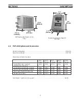
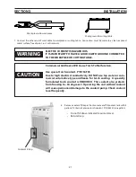
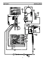
e. Connect shield gas hose (if used) to the shield gas fitting (‘B’ size left-hand thread-
ed male fitting). Hose has left-hand female fitting.
P
T
-2
6
1
2
3
4
5
f. Connect plasma cut gas (‘B’ size right-hand threaded female fitting). Hose has
right-hand male fitting.
g. Connect the switch lead.
note:
The PT-26M requires an auxiliary pilot ON switch box. Item number
1 at the left is not included in the PT-26M torch bundle. See next
page for details.
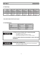
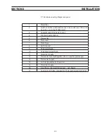
PT-26 Torch Bundle Leads
1
Switch Lead
2
Electrode Cable/Coolant Supply Hose
3
Plasma Cut Gas Hose
4
Coolant Return Hose
5
Shield Gas Hose
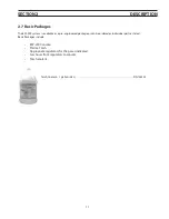
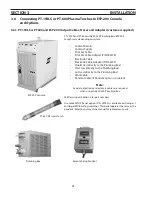
Pilot ON Switch Box.
Used with a PT-26 mechanized plasma torch.
Connect cable , same as Step (g) from the immediately above, to adapt
the mechanized version of the PT-26 plasma torch.
OFF
ON
1
2
3
4
5
1
1
Содержание ESP-200
Страница 1: ...ESP 200 Plasmarc Cutting System Instruction Manual F15 462 C 02 2008 ...
Страница 12: ...12 section 2 description ...
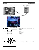
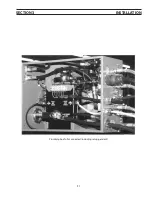
Страница 31: ...31 section 3 installation Plumbing box fully connected including setup pendant ...
Страница 32: ...32 CE 1 2 3 4 5 6 7 9 10 11 12 13 16 19 20 21 22 15 17 18 14 section 3 installation 8 ...
Страница 78: ...78 section 7 replacement parts 7 3 ESP 200 P N 36324 Outside View Front 1 2 3 4 5 6 7 8 9 10 11 12 ...
Страница 80: ...80 section 7 replacement parts 7 4 Outside View Back CE 1 2 3 4 5 6 7 8 9 10 11 CE Unit Only 12 13 ...
Страница 84: ...84 section 7 replacement parts 1 2 3 4 5 6 7 8 9 10 11 12 13 7 6 Right Inside View ...
Страница 88: ...88 section 7 replacement parts 6 1 4 5 6 R ef R ef 2 3 7 8 Back and Top Inside View ...
Страница 92: ...92 section 7 replacement parts 1 2 3 4 5 6 7 8 7 10 Remote Setup Pendant P N 37145 ...
Страница 100: ...100 notes ...


