


37
seCtIon 4
operatIon
#%
" 6 5 0 3 & 4 5 " 3 5
& / " # - &
% * 4 " # - &
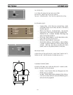
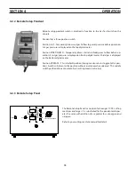
Gas Test Switch
Cut – Allows for setup of cut gas pressure and flow.
Start/Shield – Setup of gas pressures and flows.
Operate – Default position – Must be in this position for cutting.
Fault Indicator Lights
Coolant Flow – Will show low coolant flow. Light
•
will briefly show a fault when console is turned on
and then go out.
Plasma Gas Pressure -- fault indicator – low plasma
•
gas pressure. Torch will not fire when illuminated.
Interlock Fault – Indicates Remote Plumbing box
•
door is not properly closed.
P/S Temp – fault indicator – over temperature condi-
•
tion in the inverter power source.
P/S Fault – fault indicator – Not used.
•
Over/Under Voltage – fault indicator – input voltage
•
is above or below tolerances of the power source
console. Will stay shut down console until main
power switch is recycled and fault is corrected.
Main Power Switch
Controls the input power to the fan, water cooler, inverter and in-
terface circuitry. Light illuminates to indicate power is on.
Auto Restart Selector Switch
Located on the back upper right side of console. Used on mecha-
nized cutting only (CE version console).
Enable – Arc will restart after arc ON signal is lost if a
•
START signal is supplied.
Disable – START signal will be disabled if arc ON sig-
•
nal is lost and arc will not restart until START signal is
removed and re-supplied.
Содержание ESP-200
Страница 1: ...ESP 200 Plasmarc Cutting System Instruction Manual F15 462 C 02 2008 ...
Страница 12: ...12 section 2 description ...
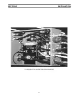
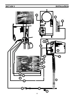
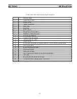
Страница 31: ...31 section 3 installation Plumbing box fully connected including setup pendant ...
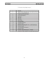
Страница 32: ...32 CE 1 2 3 4 5 6 7 9 10 11 12 13 16 19 20 21 22 15 17 18 14 section 3 installation 8 ...
Страница 78: ...78 section 7 replacement parts 7 3 ESP 200 P N 36324 Outside View Front 1 2 3 4 5 6 7 8 9 10 11 12 ...
Страница 80: ...80 section 7 replacement parts 7 4 Outside View Back CE 1 2 3 4 5 6 7 8 9 10 11 CE Unit Only 12 13 ...
Страница 84: ...84 section 7 replacement parts 1 2 3 4 5 6 7 8 9 10 11 12 13 7 6 Right Inside View ...
Страница 88: ...88 section 7 replacement parts 6 1 4 5 6 R ef R ef 2 3 7 8 Back and Top Inside View ...
Страница 92: ...92 section 7 replacement parts 1 2 3 4 5 6 7 8 7 10 Remote Setup Pendant P N 37145 ...
Страница 100: ...100 notes ...


