background image

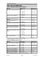
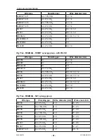
WIRE AND GAS DIMENSIONS

0460 896 274

- 87 -

© ESAB AB 2013

Wire type

Shielding gas

Wire diameter

Magnesium-alloyed aluminium wire
(ER5356)

Ar

1.0 1.2 1.6*

Magnesium-alloyed al wire (ER5183)

Ar

1.6

Silicon-alloyed aluminium wire
(ER4043)

Ar

Ar + 50% He

1.0 1.2 1.6*

1.0 1.2 1.6*

Silicon-alloyed al wire (ER4043)

Ar + 30% He

0.9 1.0 1.2

Silicon-alloyed al wire (ER4047)

Ar

1.2 1.6

Silicon bronze (ERCuSi-A)

Ar

Ar + 1% CO

2

1.0 1.2

1.0 1.2

Aluminium solid wire (ER1100)

Ar

1.2

Metal powder-filled cored wire
(E70MCW)

Ar + 8% CO

2

Ar + 18% CO

2

1.2 1.4 1.6

1.2 1.4 1.6

Metal powder cored Stainless wire (Ss
MCW)

Ar + 2% O

2

Ar + 2% CO

2

Ar + 8% CO

2

1.2


1.2


1.2


U8

2

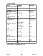
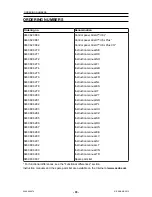
Plus - MIG/MAG welding with SHORT-/SPRAYARC

Wire type

Shielding gas

Wire diameter

Low alloy or unalloyed wire
(ER70S)

CO

2

Ar + 18% CO

2

Ar + 2% O

2

Ar + 5% O

2

+ 5% CO

2

Ar + 8% CO

2

Ar + 23% CO

2

Ar + 15% CO

2

+ 5% O

2

Ar + 16% CO

2

Ar + 25% CO

2

Ar + 2% CO

2

Ar + 5% O

2

0.8 0.9 1.0 1.2 1.6*


0.8 0.9 1.0 1.2 1.6*


0.8 0.9 1.0 1.2 1.6*


0.8 1.0 1.2 1.6*


0.8 0.9 1.0 1.2 1.6*


0.8 1.0 1.2 1.6*


0.8 0.9 1.0 1.2 1.6*


0.8 1.0 1.2 1.6*


0.8 0.9 1.0 1.2 1.6*


0.8 1.0 1.2 1.6*


1.0 1.2


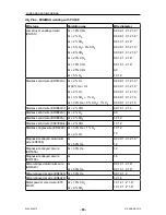
Stainless solid wire (ER316LSi) Ar + 2% O

2

Ar + 30% He + 1% O

2

Ar + 2% CO

2

Ar + 3% CO

2

+ 1% H

2

Ar + 32% He + 3% CO

2

+ 1% H

2

0.8 1.0 1.2 1.6*


0.8 1.0 1.2 1.6*


0.8 0.9 1.0 1.2 1.6*


0.8 0.9 1.0 1.2 1.6*


0.8 0.9 1.0 1.2 1.6*


Содержание Aristo U82

Страница 1: ...Aristo Instruction manual 0460 896 274 GB 20130902 Valid from program version 1 15A U82 ...

Страница 2: ...1 1 Configuration menu 14 3 1 2 Tools menu 14 3 1 3 Weld data setting menu 15 3 1 4 Measure 16 3 1 5 Weld data memory meny 17 3 1 6 Fast mode menu 17 4 MIG MAG WELDING 18 4 1 Settings in the weld data setting menu 18 4 1 1 MIG MAG welding with short sprayarc 18 4 1 2 MIG MAG welding with pulsing 19 4 1 3 MIG MAG welding with SuperPulse primary secondary short sprayarc pulsing 20 4 2 Function expla...

Страница 3: ...Delete 45 8 5 Copy 45 8 6 Edit 46 8 7 Name 48 9 CONFIGURATION MENU 49 9 1 Code lock 49 9 1 1 Lock code status 50 9 1 2 Specify edit lock code 50 9 2 Remote controls 50 9 2 1 Forget override 51 9 2 2 Configuration for digital remote control unit 51 9 2 3 Configuration for analogue remote control unit 51 9 2 4 Scale on inputs 52 9 3 MIG MAG defaults 52 9 3 1 Gun trigger mode 2 stroke 4 stroke 53 9 3...

Страница 4: ... 10 3 3 Create new folder 70 10 3 4 Copy and paste files 70 10 4 Edit setting limits 70 10 5 Edit measure limits 71 10 6 Production statistics 72 10 7 Quality functions 73 10 7 1 Store quality data 73 10 8 User defined synergic data 74 10 8 1 Specify voltage wire co ordinates 75 10 8 2 Specify valid wire gas combination 75 10 8 3 Create your own wire gas alternative 76 10 9 Calendar 77 10 10 User ...

Страница 5: ...ent must be familiar with its operation location of emergency stops its function relevant safety precautions welding and cutting or other applicable operation of the equipment 2 The operator must ensure that no unauthorised person is stationed within the working area of the equipment when it is started up no one is unprotected when the arc is struck or work is started with the equpment 3 The workp...

Страница 6: ...lectronic Equipment and its implementation in accordance with national law electrical and or electronic equipment that has reached the end of its life must be disposed of at a recycling facility As the person responsible for the equipment it is your responsibility to obtain information on approved collection stations For further information contact the nearest ESAB dealer ...

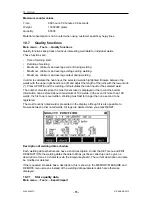
Страница 7: ...ws and an English instruction manual A 1 2 m cable is mounted on to the panel A USB memory and an extension cable are available as accessories see the ACCESSORIES chapter of this manual Instruction manuals in other languages can be downloaded from the Internet www esab com 1 Place for USB memory 2 Knob for moving cursor 3 Display 4 Soft keys 5 Menu 6 Enter 7 Knob for increasing or decreasing set v...

Страница 8: ...iew the display in an upright position The stand also acts as a mounting device enabling the control panel to be hung on the wire feed unit 2 3 USB connection External USB memories can be used to transfer programs to and from the control panel See more in the Export Import section The files that are produced in the control panel are stored as xml files The USB memory must be formatted as FAT 32 in...

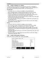
Страница 9: ...B memory in the USB connector Close the cover Turn on the power source s main switch 2 4 First step choice of language This menu appears in the display the first time you start up the equipment The control panel is set to English on delivery To select your language proceed as follows Press MENU to come to the main menu Using the left hand knob position the cursor on the CONFIGURATION row Press ENT...

Страница 10: ...the languages that are available in the control panel Position the cursor on the row for your language and press ENTER 2 5 Display The cursor The control panel s cursor is presented as a shaded field around the text with the selected text turning white The selection is displayed in the instruction manual with bold text ...

Страница 11: ...he boxes Energy saving mode To increase the life of the background lighting it is switched off after three minutes of no activity 2 5 1 Symbols in the display A The selected weld data set B S Setting limit activated M Measure limit activated C The selected wire feed unit D A fault has occurred see the Error log section in the TOOLS chapter E Recalled memory position number F Select the plus minus ...

Страница 12: ...tion the MIG MAG alternative is selected If you want to choose another alternative instead position the cursor on the correct row by stepping up or down with the left knob Then press ENTER If you want to exit the list without making a selection press QUIT 2 6 3 Settings ON OFF For some functions it is possible to set the values ON and OFF The synergy function during MIG MAG and MMA welding is an e...

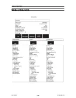
Страница 13: ...Fast mode menus The menu structures are presented in the MENU STRUCTURE appendix at the end of this manual During start up a start up screen containing information about the current program version is also displayed briefly Start up screen 3 1 Main menu In the MAIN MENU you can change welding process welding method wire type etc From this menu you can proceed to all other sub menus ...

Страница 14: ... 3 1 1 Configuration menu In the CONFIGURATION menu you can change language alter other basic settings unit of measurement etc 3 1 2 Tools menu In the TOOLS menu you can transfer files view quality and production statistics error logs etc ...

Страница 15: ...3 3 1 3 Weld data setting menu In the WELD DATA SETTING menu you can alter various welding parameters The menu has different appearances depending on which welding process is selected The example shows MIG MAG welding with short sprayarc ...

Страница 16: ...n be adjusted are always marked with or The measured values remain in the display even after welding has been completed You can move to different menus without losing the measurement values If the set value is altered when welding is not in progress the measurement value is changed to zero in order to avoid confusion TIP When pulsing you can select whether the voltage value is to be displayed as a...

Страница 17: ...d in 255 different memory positions For further information see the MEMORY MANAGEMENT chapter 3 1 6 Fast mode menu In the FAST MODE menu you can link soft keys to weld data memory positions These settings are carried out in the Configuration menu The number of the selected memory position is displayed in the top right corner For further information see the Fast mode soft keys section ...

Страница 18: ...is selected you can choose between four methods by selecting Method with the left hand knob and then pressing ENTER Choose between short sprayarc puls or superpulse and then press ENTER again 4 1 Settings in the weld data setting menu 4 1 1 MIG MAG welding with short sprayarc Settings Setting range In steps of Synergy dependent Adjustable in synergy Voltage 8 60 V 0 25 V displayed with one decimal...

Страница 19: ...e 1 2 mm The setting range is dependent on the wire feed unit used Adjusted in the configuration menu MIG MAG defaults It is not possible to select spot welding ON if gun trigger mode is 4 stroke 4 1 2 MIG MAG welding with pulsing Settings Setting range In steps of Synergy dependent Adjustable in synergy Voltage 10 50 V 0 25 V displayed with one decimal x x Wire feed speed 0 8 30 0 m min 0 1 m min...

Страница 20: ...ange is dependent on the wire feed unit used Minimal background current and pulse current are dependent on which machine type is used The synergic line on delivery solid wire ER70S shielding gas CO2 with wire 1 2 mm Adjusted in the configuration menu MIG MAG defaults It is not possible to select spot welding ON if gun trigger mode is 4 stroke 4 1 3 MIG MAG welding with SuperPulse primary secondary...

Страница 21: ... 0 1 s x Final crater filling wire feed 1 5 m min at current wire feed speed 0 1 m min x Final crater filling voltage 8 33 2 V x Final pulse current 100 max A x Final background current 12 50 A x Final frequency 20 270 Hz x Cut off pulse Burnback time 0 1 s 0 01 s x Termination Final pulse or SCT x Gas post flow 0 1 25 s 0 1 s x Setting limits 1 50 Measure limits 1 50 Spot welding OFF or ON x Spot...

Страница 22: ...able concentrated arc Inductance is set in the weld data setting menu Only applies to MIG MAG welding with short sprayarc Regulator type Affects the short circuit process and heat in the weld The setting should not be altered Pulse current The higher of the two current values in the event of pulsed current Pulse current is set in the weld data setting menu with the synergy function switched off On...

Страница 23: ...pe is set in the weld data setting menu with the synergy function switched off Only applies to MIG MAG welding with pulsing Ka Ka is the proportional element and corresponds to the regulator s amplification A low value means that the voltage is not maintained at a constant level as precisely Ka is set in the weld data setting menu internal constants with the synergy function switched off Only appl...

Страница 24: ...for editing It also determines which data are affected in measuring and remote modes The wire feed speed shown in the measure screen shows the speed in the selected phase However the voltage current and weld output are based on the measurement under both phases You can choose different synergy in the primary and secondary phases Primary or secondary phase is set in MIG MAG SET when Superpulse is s...

Страница 25: ...d data setting menu start data Only applies to robot welding Crater filling Crater filling makes a controlled reduction in the heat and size of the weld pool possible when completing the weld This makes it easier to avoid pores thermal cracking and crater formation in the weld joint In pulse welding mode it is possible to choose between pulsed and non pulsed crater filling Non pulsed crater fillin...

Страница 26: ...e results in a shorter stickout with increased risk of the arc striking back to the contact tip Burnback time is set in the weld data setting menu stop data Termination Select either Final pulse or SCT Short Circuit Termination here SCT is a function that gives small repeated short circuits at the end of welding until the wire feeding has totally stopped and contact with the workpiece has been bro...

Страница 27: ...matically sets all the necessary welding parameters After that QSet stores all the data to produce a good weld The voltage then automatically conforms to changes in the wire feed speed SPRAY When approaching the spray arc area the value for QSet must be increased Disengage the QSet function when welding with pure spray arc All settings are inherited from QSet with the exception of the voltage whic...

Страница 28: ...SuperPulse method is used for improved control of the weld pool and the solidification process The weld pool has time to solidify partially between each pulse Benefits of using SuperPulse Less sensitivity to root gap variations Better control of the weld pool during position welding Better control of penetration and penetration profile Reduced sensitivity tu uneven heat conduction SuperPulse can b...

Страница 29: ...e welded Heat Plate dimension A Pulsing in primary phase and short arc in secondary phase B Pulsing in primary phase and pulsing in secondary phase C Spray in primary phase and pulsing in secondary phase 4 3 3 Wire feed unit Only use wire feed unit Feed 3004 during SuperPulse welding Precautionary measures When using SuperPulse there is a considerable load on the wire feed unit In order of the fun...

Страница 30: ...peed is 15 m min the difference between primary and secondary wire feed speed may not exceed 6 m min Weld example A In this example we will weld a 10 mm plate with 1 2 mm aluminium wire and argon shielding gas Make the following settings using the control panel Process Phase Method Wire type Shielding gas Wire diameter Voltage Wire feed speed Phase time Superpulse Primary Short Sprayarc ER5356 Ar ...

Страница 31: ...gs using the control panel Process Phase Method Wire type Shielding gas Wire diameter Voltage Wire feed speed Phase time Superpulse Primary Pulsing ER5356 Ar 1 2 mm 1 0 V 12 5 m min 0 15 s Superpulse Secondary Pulsing ER5356 Ar 1 2 mm 2 0 V 9 0 m min 0 15 s Primary and secondary phase time are 0 15 s 0 15 s 0 3 s The difference in wire feed speed is 12 5 m min 9 0 m min 3 5 m min ...

Страница 32: ...A 1 A x Arc force 0 100 1 x Min current factor 0 100 1 x Regulator type 0 1 x Synergy OFF or ON Hot start OFF or ON x Hot start duration 1 30 1 x Hot start amplitude x Setting limits 0 50 1 Measure limits 0 50 1 Maximum current depending on which machine type is being used 5 2 MMA welding AC Settings Setting range In steps of Synergy dependent Adjustable in synergy Current 16 650 A 1 A x Arc force...

Страница 33: ...ic electrodes The setting should not be altered Regulator type Affects the short circuit process and heat in the weld The setting should not be altered Synergy Synergy for MMA welding means that the power source automatically optimises the properties for the electrode type and dimension that have been selected Synergy for MMA welding is activated in the weld data setting menu Hot start Hot start i...

Страница 34: ...e 6 1 Settings in the weld data setting menu 6 1 1 TIG welding without pulsing DC Settings Setting range In steps of HF LiftArc HF or LiftArc Live TIG start 2 4 stroke 2 stroke or 4 stroke Current 4 500 A 1 A Slope up time 0 25 s 0 1 s Slope down time 0 25 s 0 1 s Gas pre flow 0 25 s 0 1 s Gas post flow 0 25 s 0 1 s HF automatic start pulse OFF or ON HF start pulse 4 500 A 1 A Setting limits 0 50 ...

Страница 35: ...s of HF LiftArc HF or LiftArc 2 4 stroke 2 stroke or 4 stroke Current 4 500 A 1 A Slope up time 0 25 s 0 1 s Slope down time 0 25 s 0 1 s Gas pre flow 0 25 s 0 1 s Gas post flow 0 25 s 0 1 s Preheating 0 100 1 Frequency Hz Balance 1 Offset A Setting limits 0 50 1 Measure limits 0 50 1 Maximum current depending on which machine type is being used 6 2 Function explanations for settings HF start The ...

Страница 36: ...t the arc strikes when the tungsten electrode is brought into contact with the workpiece and then lifted away from it Activation of Live TIG start performed in the process menu 2 stroke A Gas pre flow B Slope up C Slope down D Gas post flow Functions when using 2 stroke control of the welding torch In the 2 stroke control mode pressing the TIG torch trigger switch 1 starts gas pre flow if used and...

Страница 37: ...ent produces a wider weld pool with better penetration into the workpiece The current is set in the measure screen weld data setting or fast mode menus Only applies to TIG welding with constant current Pulse current The higher of the two current values in the event of pulsed current When pulsing slope up and slope down are also pulsed Pulse current is set in the weld data setting menu Only applies...

Страница 38: ...G welding uses slope down by which the current falls slowly over a controlled time to avoid craters and or cracks when a weld is finished Slope down is set in the weld data setting menu Gas pre flow This controls the time during which shielding gas flows before the arc is struck Gas pre flow is set in the weld data setting menu Gas post flow This controls the time during which shielding gas flows ...

Страница 39: ... with AC Frequency Lower frequency alternating current transfers more heat to the workpiece and produces a wider weld pool Higher frequency produces a narrower arc with higher arc force narrower weld pool Frequency is set in the weld data setting menu Only applies to TIG welding with AC Balance Setting the balance between the positive electrode and negative electrode half period during alternating...

Страница 40: ...and the workpiece achieves poorer penetration Offset is set in the weld data setting menu Only applies to TIG welding with AC 6 3 Other function explanations Gas purging Gas purging is used when measuring the gas flow or to flush any air or moisture from the gas hoses before welding starts Gas purging occurs for as long as the button is held depressed and occurs without voltage or wire feed starti...

Страница 41: ...ended for power sources below 400 A 7 1 Settings in the weld data setting menu Settings Setting range In steps of Synergy dependent Adjustable in synergy Voltage 8 60 V 1 V x x Synergy OFF or ON Inductance 0 100 x Regulator type 1 12 1 x The synergic line on delivery 5 0 mm electrode carbon rod 7 2 Function explanations Voltage A higher voltage produces a wider weld pool with better penetration in...

Страница 42: ...cess It is therefore also possible to recall a weld data set from the weld data memory to the working memory Note that the working memory always contains the most recently set weld data settings They can be recalled from the weld data memory or individually altered settings In other words the working memory is never empty or zeroed Main menu Memory Weld data memory It is possible to store up to 25...

Страница 43: ...ng to store a set of weld data It will be given memory position 5 Press STORE Position 1 is displayed Turn one of the settings knobs until you reach position 5 Press STORE Select row five using one of the knobs Press STORE The following screen appears in the display Parts of the content of data set number 5 are presented at the bottom of the display ...

Страница 44: ... are going to recall a stored data set Select the row using one of the knobs Press RECALL Press YES to confirm that you want to recall data set number 5 The icon in upper right corner of the measurement display shows which memory position number has been recalled ...

Страница 45: ...oing to delete the data set we stored in an earlier example Select the data set Press DELETE Press YES to confirm that you want to delete Return to the memory menu with the NO key 8 5 Copy To copy the content of a weld data set to a new memory position proceed as follows Select the memory position you want to copy and press 2ND FUNCT ...

Страница 46: ...one of the knobs to step to the selected memory position in this case position 50 Press YES Weld data number 5 has now been copied to memory position 50 Return to the memory menu with QUIT 8 6 Edit To edit the content of a weld data set proceed as follows Select the memory position you want to edit and press 2ND FUNCTION Then press EDIT ...

Страница 47: ...eans that you are in an editing mode Select the setting you want to edit and press ENTER Select from the list and press ENTER again Press SET to move to WELD DATA SETTING Select the values you want to edit and adjust with the plus minus knobs End with QUIT The setting for weld data number 5 has now been edited and stored ...

Страница 48: ...IT Press SET to move to WELD DATA SETTING Select EDIT DESCRIPTION Press ENTER Here you have access to a keyboard that is used as follows Position the cursor on the desired keyboard character using the left hand knob and the arrow keys Press ENTER Enter a complete character string with a maximum of 40 characters in this way Press DONE to store The alternative you have named can now be seen in the l...

Страница 49: ...ults Fast mode soft buttons Fast mode soft buttons Panel remote enable WF supervision Auto save mode Trigger weld data switch Multiple wire feeders Quality functions Maintenance Unit of length Measure value frequency Register key 9 1 Code lock Main menu Configuration menu Code lock When the lock function is activated and you are in the measure screen remote mode or fast mode menu a password lock c...

Страница 50: ... menu with the keyboard where you can enter the code Press ENTER after each character and confirm the code by pressing DONE The following text box appears UNIT UNLOCKED If the code is not correct an error message is displayed that offers the option of trying again or returning to the original menu i e the measure screen or the fast mode menu If the code is correct all blocks to other menus will be...

Страница 51: ...emote control unit is being used Position the cursor on the DIGITAL OP row and press ENTER to bring up of list from which you can select an alternative BINARY CODED 32 program unit 10 PROGR 10 program unit or Welding gun with RS3 program selection 9 2 3 Configuration for analogue remote control unit Without remote control adapter When connecting a CAN based remote control unit configuration of ANA...

Страница 52: ...the potentiometer s that is to be used This is done by specifying a minimum value and a maximum value in the control panel with the plus minus knobs Note that you can set different voltage limits in synergy and non synergy modes The voltage setting in synergy is a deviation plus or minus of the synergy value In non synergy mode the voltage setting is an absolute value The value set applies to syne...

Страница 53: ...iguration menu or with a soft key in the measure screen 4 stroke There are 3 start and 2 stop positions for 4 stroke This is start and stop position 1 When resetting position 1 is selected See the 4 stroke configuration section A Gas pre flow B Hot start C Welding D Crater fill E Gas post flow Functions when using 4 stroke control of the welding torch Gas pre flow starts when the welding gun trigg...

Страница 54: ... process starts Release the trigger switch 2 Trigger controlled hot start A Gas flow B Wire feed C Gas pre flow D Hot start E Welding Press in the trigger switch 1 gas pre flow starts and hot start runs until the switch is released 2 4 stroke stop setting Time controlled crater filling with possible extension see the 4 stroke section Trigger controlled crater filling time A Gas flow B Wire feed C ...

Страница 55: ... one for key number The panel has five soft keys By pressing the 2ND FUNCT key you obtain a further five soft keys When you allocate functions to these keys they are numbered from the left as follows To allocate a new function to a soft key proceed as follows Position the cursor on the function row with the function NONE and press the soft key with the function that is to change key number Repeat ...

Страница 56: ...ow and select ON The equipment is then reconfigured automatically to match an AVC wire feed unit 9 3 6 Release pulse If the wire becomes trapped in the workpiece the system detects this A current pulse is sent out that releases the wire from the surface In order to obtain this function select RELEASE PULSE in the list under MIG MAG BASIC SETTINGS then press ENTER and select ON 9 4 MMA defaults Mai...

Страница 57: ...le Ordinarily you cannot make settings using the pushbuttons when the panel is in remote control mode When PANEL REMOTE ENABLE is ON the current wire feed or voltage can be set using the control panel and remote control If PANEL REMOTE ENABLE is used in combination with limits machine usage can be limited to a specific setting range This applies to the following settings wire feed and voltage for ...

Страница 58: ...uble clicking the welding gun s trigger It is possible to change between a maximum of 5 selected memory positions see the MEMORY MANAGEMENT chapter OFF No changeover between weld data ARC OFF The user cannot change between memory positions during welding ON The user can always change between memory positions Activating weld data switch Position the cursor on the TRIGGER WELD DATA SWITCH row and pr...

Страница 59: ...irst wire feed unit go to the MULTIPLE WIRE FEEDERS menu Press and release the trigger switch to activate the wire feed unit Then read on the first row which ID number the wire feed unit has should be 1 the first time Then select a new ID number between 2 and 4 Position the cursor on the SELECT A NEW ID NUMBER row Set the desired number between 1 and 4 by stepping with the plus minus knobs Press E...

Страница 60: ...istered here Time of welding start Duration of welding Maximum minimum and average current during welding Maximum minimum and average voltage during welding Maximum minimum and average output during welding Read more about the quality function in the Quality functions section 9 13 Maintenance Main menu Configuration menu Maintenance In this menu you set how often the contact tip is to be changed S...

Страница 61: ...plus minus knobs Measure value frequency affects only measure data in the calculations of quality data 9 16 Register key Configuration menu Register key With the function REGISTER KEY you can unlock certain functions which are not included in the basic version of the control panel For information regarding these functions see the MIG MAG section in the MENU STRUCTURE chapter In order to get access...

Страница 62: ...sition the cursor on the desired keyboard character using the left hand knob and the arrow keys Press ENTER When the character string is registred press DONE To activate the key press ACTVTE A message will be shown KEY ACTIVATED If the registration was unsuccessful the message will be INCORRECT KEY Then check the key code and try again ...

Страница 63: ...s are used to indicate that a fault has occurred in the welding process This is specified in the display with the aid of a popup menu An exclamation mark appears in the top right corner of the display NOTE disappears from the display as soon as you go into the error log menu All errors that arise during the use of the welding equipment are documented as error messages in the error log Up to 99 err...

Страница 64: ...rror EPROM There is a fault in the program memory This fault does not disable any functions Action Restart the machine If the fault persists send for a service technician 2 Microprocessor RAM error The microprocessor is unable to read write from to a certain memory position in its internal memory This fault does not disable any functions Action Restart the machine If the fault persists send for a ...

Страница 65: ...s not being overloaded 7 High primary current The power unit takes too much current from the DC voltage that supplies it The power unit is stopped and cannot be started Action Turn off the mains power supply to reset the unit If the error persists send for a service technician 12 Communication error warning The load on the system CAN bus is temporarily too high The power unit or wire feed unit may...

Страница 66: ...panel is unable to transmit information to the other units at a sufficiently high speed Action Turn off the mains power supply to reset the unit 23 Receiver buffer overflow The control panel is unable to process information from the other units at a sufficiently high speed Action Turn off the mains power supply to reset the unit 25 Incompatible weld data format Attempt to store weld data on a USB ...

Страница 67: ...he joint 71 Voltage measurement value limit passed The voltage measurement values have exceeded their limits Action Check that the voltage limit is correctly set as well as the quality of the joint 72 Power measurement value limit passed The power measurement values have exceeded their limits Action Check that the power limit is correctly set as well as the quality of the joint 73 WF current measu...

Страница 68: ...anager you can process information both in a USB memory C File manager makes it possible to delete and copy weld data and quality data manually When the USB memory is inserted the display shows the basic folder of the memory if no folder already has been choosen The control panel remembers where you were the last time you used file manager so that you return to the same place in the file structure...

Страница 69: ... and press ALT This list is displayed when you have pressed ALT 10 3 1 Delete a file folder Select the file or folder that is to be deleted and press ALT Select DELETE and press ENTER The file folder is now removed In order to delete a folder it must be empty i e first delete the files contained in the folder 10 3 2 Rename a file folder Select the file or folder that is to be renamed and press ALT...

Страница 70: ...NTER Position the cursor in the folder in which the copied file is to be located and press ALT Select PASTE and press ENTER The copy is saved as Copy of plus the original name e g Copy of WeldData awd 10 4 Edit setting limits Main menu Tools Edit settings limits In this menu you set your own max and min values for various welding methods The limits cannot be above or below the values for which the...

Страница 71: ... There are 50 storage points Select the row for an empty storage point and press ENTER Select process by pressing ENTER Then select welding process from the list that appears and then press ENTER again The following values can be selected For MIG MAG voltage min max min average max average current min max min average max average output min max min average max average wire feed unit current min max...

Страница 72: ... since the most recent reset They will also keep track of the arc time and the amount of material used in the most recent weld For information purposes the melted wire material per length unit that has been calculated and when the most recent reset occurred are also displayed The number of welds does not increase if the arc time has been shorter than 1 second For this reason the amount of material...

Страница 73: ...nput for the selected weld The number of welds since the most recent reset is displayed in the row at the bottom Information can be stored about a maximum of 100 welds In the event of more than 100 welds the first one is overwritten Welding must last for longer than one second to be registered The most recently noted weld is presented in the display although it is also possible to browse between o...

Страница 74: ...el is now saved on the USB memory The file is in a folder called QData QData is created automatically when you insert a USB memory Read more about the quality function in the Quality function section 10 8 User defined synergic data Main menu Tools User defined synergic data It is possible to create your own synergic lines with respect to wire feed speed and voltage A maximum of ten such synergic l...

Страница 75: ...than the nearest preceding weld data number The welding parameters inductance and regulator type must have the same value in all four weld data numbers Define the number of co ordinates that are required and then proceed to the Specify valid wire gas combination section Pulsing Bring up the main menu and select the MIG MAG method PULSING Key in the desired values for voltage and wire feed speed fo...

Страница 76: ...nce When you create a new synergic line for the pulsing method you therefore always receive a warning message stating that a corresponding line has not been created for the short sprayarc method The message reads WARNING No corresponding synergic line for short sprayarc 10 8 3 Create your own wire gas alternative The lists of wire gas alternatives can be extended with up to ten alternatives of you...

Страница 77: ...e working memory 10 9 Calendar Main menu Tools Calendar Date and time are set here Select the row that is to be set year month day hour minutes and seconds Set the correct value using one of the right hand knobs Press SET 10 10 User accounts Main menu Tools User accounts Occasionally it is particularly important from a quality perspective that the power source cannot be used by unauthorised partie...

Страница 78: ... activated you are asked in the display to enter your password If you choose not to have this function but instead want the power source and control panel to be unlocked for all users select USER ACCOUNTS OFF Change user When USER ACCOUNTS is ON this menu is visible It gives a possibility to change user Enter a password for a user and log in or choose QUIT to return to the tools menu 10 11 Unit in...

Страница 79: ... European standards 60974 1 and 60974 10 It is the obligation of the service unit which has carried out the service or repair work to make sure that the product still conforms to the said standard Spare parts may be ordered through your nearest ESAB dealer see the back cover of this document When ordering please state product type serial number designation and spare part number in accordance with ...

Страница 80: ...MENU STRUCTURE 0460 896 274 80 ESAB AB 2013 MENU STRUCTURE ...

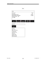
Страница 81: ...MENU STRUCTURE 0460 896 274 81 ESAB AB 2013 ...

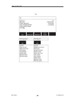
Страница 82: ...MENU STRUCTURE 0460 896 274 82 ESAB AB 2013 ...

Страница 83: ...MENU STRUCTURE 0460 896 274 83 ESAB AB 2013 ...

Страница 84: ...MENU STRUCTURE 0460 896 274 84 ESAB AB 2013 ...

Страница 85: ...s Functions U82 Basic U82 Plus Super Pulse No Yes Limit editor Yes Yes File manager No Yes Auto save mode No Yes Release pulse Yes Yes Synergic lines Basic package 111 lines Complete no of available lines User defined synergic data No Yes Production statistics No Yes ...

Страница 86: ...1 4 1 6 1 2 1 4 1 6 Rutile flux cored wire E70 RFCW Ar 18 CO2 1 2 1 4 1 6 Basic flux cored wire E70 BFCW CO2 Ar 18 CO2 1 2 1 4 1 6 1 2 1 4 1 6 Metal powder cored stainless wire Ss MCW Ar 8 CO2 Ar 2 O2 Ar 18 CO2 Ar 2 CO2 1 2 1 2 1 2 1 2 Silicon bronze ERCuSi A Ar Ar 1 O2 1 0 1 2 1 0 1 2 Only for Mig 4000i 4001i 4002c 5000i 5002c 6502c U82 Basic MIG MAG welding with PULSE Wire type Shielding gas Wir...

Страница 87: ... 1 4 1 6 1 2 1 4 1 6 Metal powder cored Stainless wire Ss MCW Ar 2 O2 Ar 2 CO2 Ar 8 CO2 1 2 1 2 1 2 U82 Plus MIG MAG welding with SHORT SPRAYARC Wire type Shielding gas Wire diameter Low alloy or unalloyed wire ER70S CO2 Ar 18 CO2 Ar 2 O2 Ar 5 O2 5 CO2 Ar 8 CO2 Ar 23 CO2 Ar 15 CO2 5 O2 Ar 16 CO2 Ar 25 CO2 Ar 2 CO2 Ar 5 O2 0 8 0 9 1 0 1 2 1 6 0 8 0 9 1 0 1 2 1 6 0 8 0 9 1 0 1 2 1 6 0 8 1 0 1 2 1 6 ...

Страница 88: ... RFCW CO2 Ar 18 CO2 1 2 1 4 1 6 1 2 1 4 1 6 Basic flux cored wire E70 BFCW CO2 Ar 18 CO2 SELF SHIELDING 1 0 1 2 1 4 1 6 1 0 1 2 1 4 1 6 1 2 1 6 Stainless flux cored wire Ss RFCW Ar 18 CO2 Ar 8 CO2 SELF SHIELDING 1 2 1 2 1 6 2 4 Duplex rutile flux cored wire E2209 Ar 18 CO2 1 2 Metal powder cored stainless wire Ss MCW Ar 8 CO2 Ar 2 O2 Ar 18 CO2 Ar 2 CO2 1 2 1 2 1 2 1 2 ERNiCrMo Ar 50 He 0 9 Silicon...

Страница 89: ...9 1 0 1 2 1 6 0 8 0 9 1 0 1 2 1 6 0 8 0 9 1 0 1 2 1 6 Stainless solid wire ER308LSi Ar 2 CO2 0 9 1 0 1 2 1 6 Stainless solid wire ER308LSi Ar 2 O2 0 9 Stainless solid wire ER309LSi Ar 2 CO2 1 0 1 2 Stainless solid wire SS309MoL Ar 2 CO2 1 0 1 2 Stainless duplex wire ER2209 Ar 30 He 1 O2 Ar 2 O2 1 0 1 2 1 0 Magnesium alloyed aluminium wire ER5356 Ar Ar 50 He 0 8 0 9 1 0 1 2 1 6 1 2 Magnesium alloye...

Страница 90: ...uminium solid wire ER1100 Ar 1 2 Only for Mig 4000i 4001i 4002c 5000i 5002c 6502c MMA welding Electrode type Electrode diameter Basic 1 6 2 0 2 5 3 2 4 0 4 5 5 0 5 6 6 0 Rutile 1 6 2 0 2 5 3 2 4 0 4 5 5 0 5 6 6 0 7 0 Cellulose 2 5 3 2 Only for Mig 4000i 4001i 5000i Carbon arc air Electrode diameters mm 4 0 5 0 6 0 10 0 13 0 U82 Plus MIG MAG ROBOT synergy group with SHORT SPRAYARC Wire type Shieldi...

Страница 91: ...LSE Wire type Shielding gas Wire diameter mm ER5356 Ar 1 2 1 6 ER4043 Ar 1 2 1 6 ERCuAl A1 Ar 1 0 ERCuSi A Ar 1 CO2 1 0 ER70S Ar 18 CO2 0 8 0 9 1 0 1 2 ER70S Ar 8 CO2 0 8 0 9 1 0 1 2 SS 307 Ar 2 CO2 0 8 1 0 1 2 ER308LSi Ar 2 CO2 0 8 0 9 1 0 1 2 SS 430LNb Ar 2 CO2 0 8 1 0 SS 430Ti Ar 2 CO2 0 9 1 0 U82 Plus MIG MAG SAT synergy group Wire type Shielding gas Wire diameter mm Work area m min ER70S Ar 8...

Страница 92: ...Fe MCW 14 11 Ar 18 CO2 1 2 7 14 Fe MCW 14 11 Ar 8 CO2 1 4 5 9 12 Fe MCW 14 11 Ar 18 CO2 1 4 6 6 12 SS 430LNb Ar 2 CO2 1 0 14 2 25 SS 430Ti Ar 2 CO2 0 9 16 27 SS 430Ti Ar 2 CO2 1 0 14 2 25 SS 430LNb Ti Ar 2 CO2 1 0 14 2 27 5 ER308LSi Ar 2 CO2 1 0 15 27 5 ER308LSi Ar 2 CO2 0 9 16 28 ER308LSi Ar 2 CO2 0 8 18 29 5 ...

Страница 93: ... Aristo U82 Plus I O Instruction manual SE Instruction manual DK Instruction manual NO Instruction manual FI Instruction manual GB Instruction manual DE Instruction manual FR Instruction manual NL Instruction manual ES Instruction manual IT Instruction manual PT Instruction manual GR Instruction manual PL Instruction manual HU Instruction manual CZ Instruction manual SK Instruction manual RU Instr...

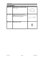
Страница 94: ...2013 ACCESSORIES 0460 877 891 Extension cable connectors included 7 5 m 12 poles 0457 043 880 Adapter set 230 V AC 12 V DC for control box for training with the control box disconnected from the machine 0462 062 001 USB Memory stick Gb 2 ...

Страница 95: ...ACCESSORIES 0460 896 274 95 ESAB AB 2013 ...

Страница 96: ...el 34 91 878 3600 Fax 34 91 802 3461 SWEDEN ESAB Sverige AB Gothenburg Tel 46 31 50 95 00 Fax 46 31 50 92 22 ESAB International AB Gothenburg Tel 46 31 50 90 00 Fax 46 31 50 93 60 SWITZERLAND ESAB AG Dietikon Tel 41 1 741 25 25 Fax 41 1 740 30 55 UKRAINE ESAB Ukraine LLC Kiev Tel 38 044 501 23 24 Fax 38 044 575 21 88 North and South America ARGENTINA CONARCO Buenos Aires Tel 54 11 4 753 4039 Fax 5...

Отзывы: