SmartEdge 600 Router Hardware Guide
Connect and route the cables:
1.
Put on an antistatic wrist strap, and attach it to an appropriate grounded
surface. Do not attach the wrist strap to a painted surface; an ESD
convenience jack is located in the lower right corner of the air intake panel
on the front of the chassis.
2.
Connect and route the management access cables, depending on the
type of management access you have selected. To connect and route
the cables:
a
Thread the system ends of the cables through the lowest opening in
the cable management bracket at the right side of the card slot.
b
Insert each cable in the appropriate connector on the card.
c
Tie-wrap the cables from each controller card to form a bundle, and
then tie each bundle to the rack.
3.
Starting with the line card installed in slot 6, connect and route the line
card cables:
a
Thread the system ends of the cables through an opening in the cable
management bracket at the right side of the card slot. Select an
opening that provides space for all cables to be connected to this card.
b
Insert each cable in the appropriate connector on the card.
c
Tie-wrap the cables to form a bundle, and then tie each bundle to the
rack.
4.
Connect and route the breakout cables for the FE–GE line cards:
a
Thread the MRJ21 connector end of a breakout cable through the cable
management bracket at the right side of the card slot.
b
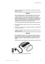
Attach the breakout cable to the right-most connector to be cabled on
an FE–GE line card. Position the connector so that the incised label
“KEY” on the connector is on the bottom side of the connector as you
face the chassis; see Figure 21.
Caution!
Risk of equipment damage. The cable connector is keyed to ensure
that you insert it with the correct orientation into the front panel
connector. However, it is possible to force an incorrectly positioned
cable connector into the connector on the front panel. To reduce the
risk of overriding the key, ensure that the incised “KEY” label is on the
left side of the connector.
44
27/153 30-CRA 119 1170/1 Uen A
|
2010-04-09
Содержание SmartEdge 600
Страница 1: ...SmartEdge 600 Router Hardware Guide Release 6 3 INSTALLATION 27 153 30 CRA 119 1170 1 Uen A ...
Страница 6: ...SmartEdge 600 Router Hardware Guide 27 153 30 CRA 119 1170 1 Uen A 2010 04 09 ...
Страница 26: ...SmartEdge 600 Router Hardware Guide 20 27 153 30 CRA 119 1170 1 Uen A 2010 04 09 ...
Страница 108: ...SmartEdge 600 Router Hardware Guide 102 27 153 30 CRA 119 1170 1 Uen A 2010 04 09 ...
Страница 112: ...SmartEdge 600 Router Hardware Guide 106 27 153 30 CRA 119 1170 1 Uen A 2010 04 09 ...

