Installing the Hardware
c
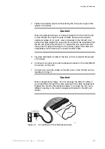
Tighten the captive screws without letting the front panel support the
weight of the cable.
Caution!
Risk of equipment damage. A breakout cable for the 60 10/100 ports
on the FE–GE line cards is made of AWG #24 wire and includes
individual cables for 12 ports; when connected to the FE–GE front
panel, the cable weight can cause the front panel to be separated from
the FE–GE printed circuit board. To reduce the risk, never allow the
front panel to support the weight of the cable; support the cable and
immediately route it before you connect another cable.
d
Tie-wrap the breakout cable to the rack so that it supports the weight
of the cable.
e
Continue to connect and route the breakout cables for the other MRJ21
connectors on the card.
f
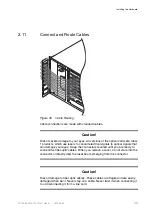
Connect and route the cables for the GE ports on the FE–GE card as
described in Step 3
Caution!
Risk of equipment damage. You can damage the GE port cables if
you thread them through the same opening in the cable management
bracket that contains the breakout cables. To reduce the risk, use a
different opening in the cable management bracket for the GE port
cables.
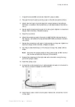
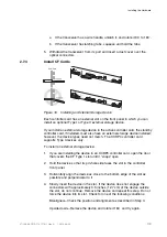
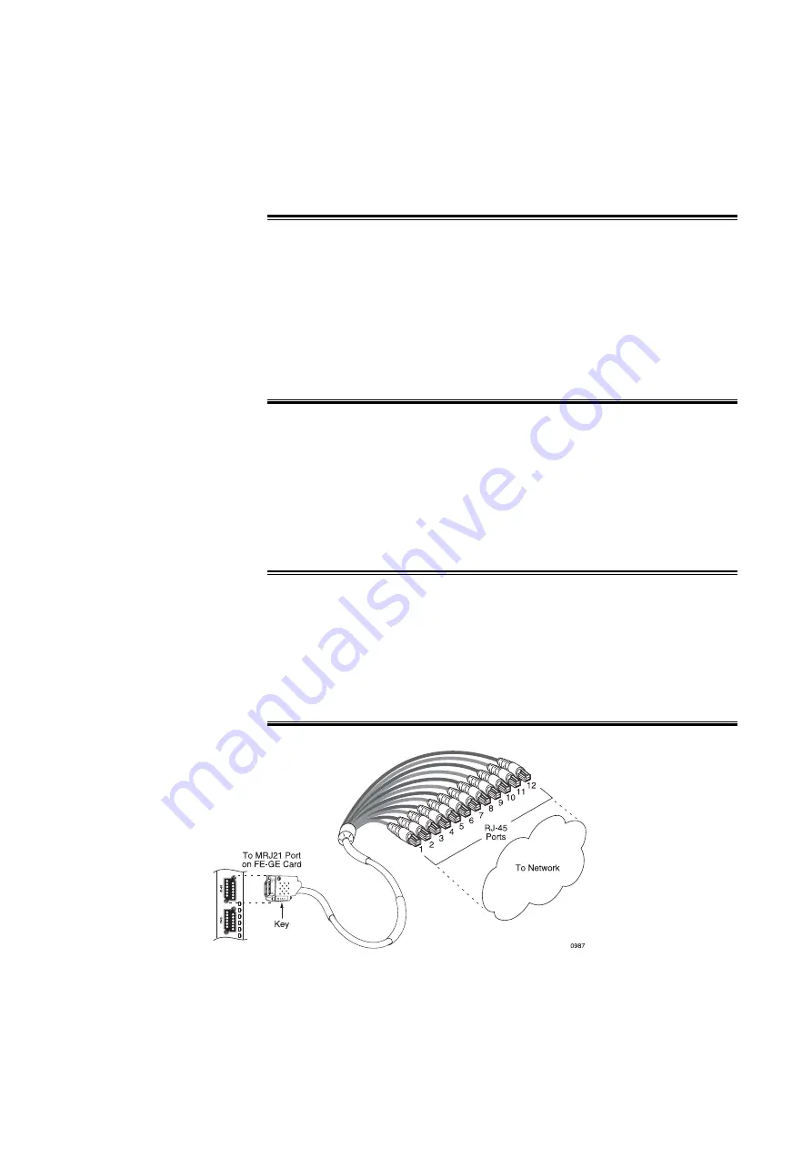
Figure 21
Connecting an FE–GE Breakout Cable
45
27/153 30-CRA 119 1170/1 Uen A
|
2010-04-09
Содержание SmartEdge 600
Страница 1: ...SmartEdge 600 Router Hardware Guide Release 6 3 INSTALLATION 27 153 30 CRA 119 1170 1 Uen A ...
Страница 6: ...SmartEdge 600 Router Hardware Guide 27 153 30 CRA 119 1170 1 Uen A 2010 04 09 ...
Страница 26: ...SmartEdge 600 Router Hardware Guide 20 27 153 30 CRA 119 1170 1 Uen A 2010 04 09 ...
Страница 108: ...SmartEdge 600 Router Hardware Guide 102 27 153 30 CRA 119 1170 1 Uen A 2010 04 09 ...
Страница 112: ...SmartEdge 600 Router Hardware Guide 106 27 153 30 CRA 119 1170 1 Uen A 2010 04 09 ...

