


Chapter 3 Disassembly and Assembly
Rev. A
3-13
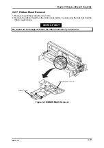
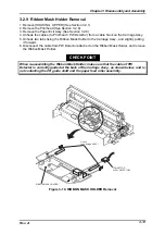
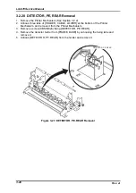
3.2.9 Ribbon Mask Holder Removal
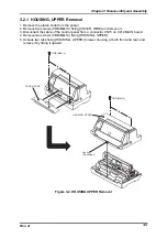
1. Remove [HOUSING, UPPER] (See Section 3.2.1)
2. Remove the Printhead (See Section 3.2.6)
3. Remove the Paper Exit Assy.(See Section 3.2.8)
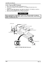
4. Unhook the cables (to Printhead / PW Detector) from a cable hook on the Carriage Assy.
5. Unhook two tabs fixing the Ribbon Mask Holder to the Carriage Assy., and slightly pulling
it forward.
6. Disconnect the cable from PW Detector attached on the Ribbon Mask Holder, and remove
the Ribbon Mask Holder.
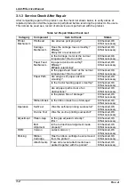
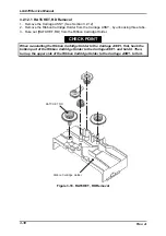
When re-assembling the Ribbon Mask Holder, make sure that the cable of PW
Detector is correctly guided at the back of the Carriage Assy., as shown below, and is
not contacting the CR guide shaft and the paper feed roller assembly.
CHECK POINT
Hooks
(on Carriage ASSY.)
CONNECTOR
(to PW DETECTOR)
RIBBON MASK HOLDER
Figure 3-10. RIBBON MASK HOLDER Removal
Содержание LQ 670 - B/W Dot-matrix Printer
Страница 1: ...EPSON IMPACT DOT MATRIX PRINTER EPSON LQ 670 SERVICE MANUAL SEIKO EPSON CORPORATION 4007875 ...
Страница 5: ...v REVISION SHEET Revision Issued Data Contents Rev A May 28 1997 First issue ...
Страница 114: ...Chapter 6 Maintenance 6 1 Preventive Maintenance 6 1 ...
Страница 116: ...LQ 670 Service Manual Rev A 6 2 Figure 6 1 Lubrication Points ...
Страница 122: ...LQ 670 Service Manual Rev A A 5 A 2 Circuit Diagram Figure A 2 C214Main Board Circuit Diagram ...
Страница 123: ...Appendix Rev A A 6 Heat Sink Q1 D51 Figure A 3 C214PSB Board Circuit Diagram ...
Страница 124: ...LQ 670 Service Manual Rev A A 7 Heat Sink Q1 D51 Figure A 4 C214PSE Board Circuit Diagram ...
Страница 125: ...Appendix Rev A A 8 A 3 Component Layout Figure A 5 C214 Main Board Component Layout ...
Страница 126: ...LQ 670 Service Manual Rev A A 9 Figure A 6 C214 PSB Board Component Layout Figure A 7 C214 PSE Board Component Layout ...
Страница 127: ...Appendix Rev A A 10 A 4 Exploded Diagram Figure A 8 Exploded Diagram ...
Страница 128: ...LQ 670 Service Manual Rev A A 11 Figure A 9 Exploded Diagram ...
Страница 129: ...Appendix Rev A A 12 Figure A 10 Exploded Diagram ...
Страница 135: ...EPSON SEIKO EPSON CORPORATION ...


