LQ-670 Service Manual
Rev. A
5-12
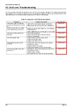
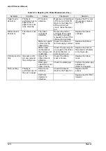
Symptom
Condition
Cause
Checkpoint
Solution
Normal voltage
is not output.
All output voltage
is defective.
•
If +42V is not
output normally,
other voltages
become
abnormal.
T1 is
defective.
Check the voltage (pin 6,
7)which is charged to the
coil of the primary side.
Also, check the output
voltage on the secondary
side.
•
It is possible that output
voltage of T1 is not out
because of defective
elements on the end of the
secondary side.
Replace the power
supply board, T1 or
appropriate parts.
Diode D51 is
defective.
Check if
+
42V is output
between C51/C51.
Replace the power
supply
board,C51/51 or
appropriate parts.
Power supply
control signal
line(PSC) is
shorted.
Check is PSC line, CN2; or
harness of 10-pin is not fell
down to GND.
Replace the power
supply board,
harness or
appropriate parts.
All the output
voltage is
defective
Over current
protection
circuit is
defective.
Check if the transistor Q28
is On.(Collector is Gp level)
•
If the transistor is Off,
elements in the end of PC2
circuit or main switching
circuit(Q1, Q31) is
defective.
•
If it is on, elements around
Q53 or Q54 are defective.
Replace the power
supply board, Q82,
Q53, Q54 or
appropriate parts.
Over voltage
protection
circuit is
defective.
❑
Check if the transistor
Q82 is On or not. (Collector
is Gp level)
•
If it is Off, elements in the
end of PC2 circuit or main
switching circuit(Q1, Q31)
is defective.
•
If it is On, the elements
around Q54, Q55, ZD52,
ZD87 or Q82 are defective.
❑
If +5V is too high, Q82
becomes On.
•
If it is Off, elements in the
end of PC2 circuit or main
switching circuit(Q1, Q31)
is defective.
•
If it is on, elements around
Q54, Q55, ZD53 or Q82 are
defective.
Since the PC2 is photo
thylistor, once it becomes
on, it does not become Off
until electric is discharged
from C11. Therefore, it
takes sometime until
electricity goes through
again.
Replace the power
supply board, Q82,
Q54, Q55 or
appropriate parts.
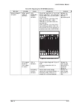
Table 5-9. Repairing C214PSB Board (Con.)
Содержание LQ 670 - B/W Dot-matrix Printer
Страница 1: ...EPSON IMPACT DOT MATRIX PRINTER EPSON LQ 670 SERVICE MANUAL SEIKO EPSON CORPORATION 4007875 ...
Страница 5: ...v REVISION SHEET Revision Issued Data Contents Rev A May 28 1997 First issue ...
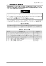
Страница 114: ...Chapter 6 Maintenance 6 1 Preventive Maintenance 6 1 ...
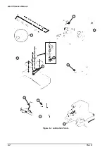
Страница 116: ...LQ 670 Service Manual Rev A 6 2 Figure 6 1 Lubrication Points ...
Страница 122: ...LQ 670 Service Manual Rev A A 5 A 2 Circuit Diagram Figure A 2 C214Main Board Circuit Diagram ...
Страница 123: ...Appendix Rev A A 6 Heat Sink Q1 D51 Figure A 3 C214PSB Board Circuit Diagram ...
Страница 124: ...LQ 670 Service Manual Rev A A 7 Heat Sink Q1 D51 Figure A 4 C214PSE Board Circuit Diagram ...
Страница 125: ...Appendix Rev A A 8 A 3 Component Layout Figure A 5 C214 Main Board Component Layout ...
Страница 126: ...LQ 670 Service Manual Rev A A 9 Figure A 6 C214 PSB Board Component Layout Figure A 7 C214 PSE Board Component Layout ...
Страница 127: ...Appendix Rev A A 10 A 4 Exploded Diagram Figure A 8 Exploded Diagram ...
Страница 128: ...LQ 670 Service Manual Rev A A 11 Figure A 9 Exploded Diagram ...
Страница 129: ...Appendix Rev A A 12 Figure A 10 Exploded Diagram ...
Страница 135: ...EPSON SEIKO EPSON CORPORATION ...

