LQ-670 Service Manual
Rev. A
1-30
1.5 Main Components
This printer consists of the following components.
C214MAIN Board
C214 PSB/PSE Board
C214 PNL Board
Printer Mechanism(M-5060)
Housing
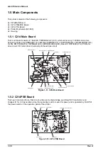
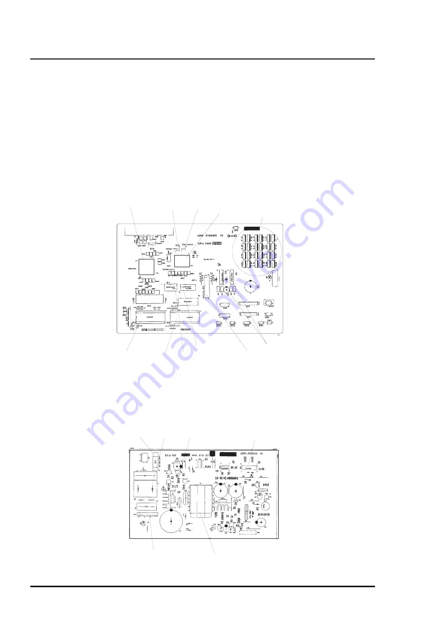
1.5.1 C214 Main Board
This main board consists of 16bitCPU TMP96C041AF (IC11) which is driven by 17.20MHz clock drive
frequency, Gate array E05B42(IC10), 2/4M Flash-EPROM(IC7), or 8M PROM(IC8), 4/8/32M MROM (IC4)
for CG, 8M PROM (IC5), 1MPSRAM (IC6), EEPROM 93C46(IC9), Reset IC RST592D (C12), PF Motor
drive circuit, CR motor drive circuit and print head drive circuit.
1.5.2 C214PSB Board
This board consists of fuse, filter circuit, primary side diode bridge, switching FET, transformer and
chopper IC for +5V generation. Also, the secondary switch is used for power and is operated by On/Off of
the power switch on the operation panel of the printer.
Gate Array(IC10)
Reset IC(IC12)
EEPROM(IC9)
CPU(IC11)
Print Head Driver
PROM(IC8)
PROM(IC5)
Flash-EPROM(IC7)
PSRAM(IC5)
CR Motor Driver IC
PF Motor Driver IC
Figure 1-11. C214 Main Board
Fuse
Filter Circuit
SwitchingFET
Diode Bridge
Chopper IC for +5V generation
Transformaer
Figure 1-12. C214 PSB Board
Содержание LQ 670 - B/W Dot-matrix Printer
Страница 1: ...EPSON IMPACT DOT MATRIX PRINTER EPSON LQ 670 SERVICE MANUAL SEIKO EPSON CORPORATION 4007875 ...
Страница 5: ...v REVISION SHEET Revision Issued Data Contents Rev A May 28 1997 First issue ...
Страница 114: ...Chapter 6 Maintenance 6 1 Preventive Maintenance 6 1 ...
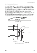
Страница 116: ...LQ 670 Service Manual Rev A 6 2 Figure 6 1 Lubrication Points ...
Страница 122: ...LQ 670 Service Manual Rev A A 5 A 2 Circuit Diagram Figure A 2 C214Main Board Circuit Diagram ...
Страница 123: ...Appendix Rev A A 6 Heat Sink Q1 D51 Figure A 3 C214PSB Board Circuit Diagram ...
Страница 124: ...LQ 670 Service Manual Rev A A 7 Heat Sink Q1 D51 Figure A 4 C214PSE Board Circuit Diagram ...
Страница 125: ...Appendix Rev A A 8 A 3 Component Layout Figure A 5 C214 Main Board Component Layout ...
Страница 126: ...LQ 670 Service Manual Rev A A 9 Figure A 6 C214 PSB Board Component Layout Figure A 7 C214 PSE Board Component Layout ...
Страница 127: ...Appendix Rev A A 10 A 4 Exploded Diagram Figure A 8 Exploded Diagram ...
Страница 128: ...LQ 670 Service Manual Rev A A 11 Figure A 9 Exploded Diagram ...
Страница 129: ...Appendix Rev A A 12 Figure A 10 Exploded Diagram ...
Страница 135: ...EPSON SEIKO EPSON CORPORATION ...

