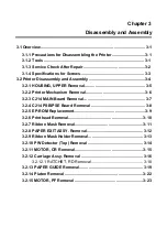
Chapter 3 Disassembly and Assembly
Rev. A
3-1
3.1 Overview
This section describes procedures for disassembling the main components of EPSON LQ-
670. Unless otherwise specified, disassembled units or components can be reassembled by
reversing the disassembly procedure. Therefore, no assembly procedures are included in
this section. Precautions for any disassembly or assembly procedure are described under
the heading "WORK POINT". Any adjustments required after disassembling the units are
described under the heading "REQUIRED ADJUSTMENT".
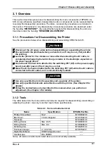
3.1.1 Precautions for Disassembling the Printer
See the precautions below when disassembling and assembling EPSON LQ-670.
Disconnect the AC power cable before disassembling or assembling the printer.
Be careful with the printhead when you handle it, as it may be very hot just after
the printing.
Leave the printer for five minutes or more after disconnecting the AC cable, to
completely discharge high electric charge remains in the electrolyte capacitor on
the power supply board.
Do not touch the heat sink, attached to the switching FET (Q1) on the power supply
board, just after power off as it may be very hot.
Never touch the heat sink attached to the switching FET (Q1) while the AC cable is
connected to the AC outlet, as it is not electrically isolated.
Use only specified tools for disassembly and assembly of the printer.
Use only specified lubricants and adhesives with the printer. (See Chapter 6 for
details)
Follow the instructions only described in this manual when you perform an
adjustment. (See Chapter 4 for details)
3.1.2 Tools
The table below lists the tools and the instruments required for disassembling, assembling or
adjusting the printer. Use only tools that meets these specifications.
Table 3-1. Tool and Instrument List
Name
Specification
EPSON Part No.
Phillips Screwdriver
No.2
B743800200
Box Driver
7.0mm diagonal
B741700200
Tweezers
B741000100
E-Ring Holder
Size : #2.5
B740800400
E-Ring Holder
Size : #4
B740800600
Soldering Iron
B740200100
Thickness Gauge
t = 0.42 mm
B776702201
Digital Multi-Meter
OHM/Voltage/Current
-----
Oscilloscope
Min. 50MHz
-----
Note) All tools and instruments listed above are commercially available.
WARNING
CAUTION
Содержание LQ 670 - B/W Dot-matrix Printer
Страница 1: ...EPSON IMPACT DOT MATRIX PRINTER EPSON LQ 670 SERVICE MANUAL SEIKO EPSON CORPORATION 4007875 ...
Страница 5: ...v REVISION SHEET Revision Issued Data Contents Rev A May 28 1997 First issue ...
Страница 114: ...Chapter 6 Maintenance 6 1 Preventive Maintenance 6 1 ...
Страница 116: ...LQ 670 Service Manual Rev A 6 2 Figure 6 1 Lubrication Points ...
Страница 122: ...LQ 670 Service Manual Rev A A 5 A 2 Circuit Diagram Figure A 2 C214Main Board Circuit Diagram ...
Страница 123: ...Appendix Rev A A 6 Heat Sink Q1 D51 Figure A 3 C214PSB Board Circuit Diagram ...
Страница 124: ...LQ 670 Service Manual Rev A A 7 Heat Sink Q1 D51 Figure A 4 C214PSE Board Circuit Diagram ...
Страница 125: ...Appendix Rev A A 8 A 3 Component Layout Figure A 5 C214 Main Board Component Layout ...
Страница 126: ...LQ 670 Service Manual Rev A A 9 Figure A 6 C214 PSB Board Component Layout Figure A 7 C214 PSE Board Component Layout ...
Страница 127: ...Appendix Rev A A 10 A 4 Exploded Diagram Figure A 8 Exploded Diagram ...
Страница 128: ...LQ 670 Service Manual Rev A A 11 Figure A 9 Exploded Diagram ...
Страница 129: ...Appendix Rev A A 12 Figure A 10 Exploded Diagram ...
Страница 135: ...EPSON SEIKO EPSON CORPORATION ...

