


Chapter 2 Operating Principles
Rev. A
2-16
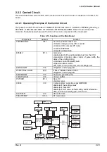
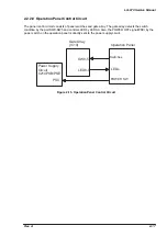
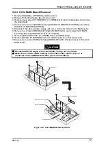
2.2.2.6 CR Motor Driver Circuit
The CR motor driver circuit of this printer consists of CPU, gate array, CR motor drive IC SLA7024M (IC3)
and CR motor. The CPU sends phase data; INA, /INA, INB and/INB from the port PGO0-3 to the CR
motor IC. The current setting is de-coded in the CRFA0-3 and CRFB0-3 of the gate array by the CPU and
is output to the CR motor drive IC. The CR motor driver IC outputs phase signals; CRA, /CRA, CRB, /CRB
to the CR motor. The CR motor is driven at open loop control uni-pola rated current type by the drive IC.
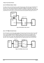
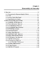
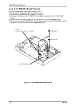
2.2.2.7 PF Motor Driver Circuit
The PF motor driver circuit of this printer consists of CPU, gate array, PF motor drive IC(IC1, IC2) and PF
motor. The CPU sends phase data(PFPHASEA/B) to the PF motor drive IC via the gate array. Also, the
current control signals;PF10A/1A, PF10B/1B are outputs to the PF motor drive IC via gate array for
current setting. The PF motor drive IC outputs phase signals; PFA, /PFA, PFB, /PFB to the PF motor.
The CR motor is driven at open loop control bi-pola rated current type by the driver ICSLA7024M(IC3).
Also, the current is controlled by the /PFHOLD signal from the gate array when the reset is performed.
REFA/B
INA
/INA
INB
/INB
CRA
CR/A
CRB
CR/B
PGO0-3
CRRFA0-3
CRRFB0-3
OUTA
/OUTA
OUTB
/OUTB
CR Motor
Gate Array
(IC10)
CPU
(IC11)
CR Motor Drive
(IC3)
Figure 2-13.CR Motor Driver Circuit
PFA
PF/A
PFB
PF/B
OUTA
OUTB
REF
I00/1
PHASE
/PFHOLD
PFI0A/1A
PFI0B/1B
PFPHASEA/B
CPU
(IC11)
Gate Array
(IC10)
PF Motor Drive IC
(IC1, IC2)
PF Motor
Figure 2-14.PF Motor Driver Circuit
Содержание LQ 670 - B/W Dot-matrix Printer
Страница 1: ...EPSON IMPACT DOT MATRIX PRINTER EPSON LQ 670 SERVICE MANUAL SEIKO EPSON CORPORATION 4007875 ...
Страница 5: ...v REVISION SHEET Revision Issued Data Contents Rev A May 28 1997 First issue ...
Страница 114: ...Chapter 6 Maintenance 6 1 Preventive Maintenance 6 1 ...
Страница 116: ...LQ 670 Service Manual Rev A 6 2 Figure 6 1 Lubrication Points ...
Страница 122: ...LQ 670 Service Manual Rev A A 5 A 2 Circuit Diagram Figure A 2 C214Main Board Circuit Diagram ...
Страница 123: ...Appendix Rev A A 6 Heat Sink Q1 D51 Figure A 3 C214PSB Board Circuit Diagram ...
Страница 124: ...LQ 670 Service Manual Rev A A 7 Heat Sink Q1 D51 Figure A 4 C214PSE Board Circuit Diagram ...
Страница 125: ...Appendix Rev A A 8 A 3 Component Layout Figure A 5 C214 Main Board Component Layout ...
Страница 126: ...LQ 670 Service Manual Rev A A 9 Figure A 6 C214 PSB Board Component Layout Figure A 7 C214 PSE Board Component Layout ...
Страница 127: ...Appendix Rev A A 10 A 4 Exploded Diagram Figure A 8 Exploded Diagram ...
Страница 128: ...LQ 670 Service Manual Rev A A 11 Figure A 9 Exploded Diagram ...
Страница 129: ...Appendix Rev A A 12 Figure A 10 Exploded Diagram ...
Страница 135: ...EPSON SEIKO EPSON CORPORATION ...


