Chapter 1 Product Description
Rev. A
1-25
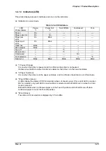
1.4.1.3 Indicators(LED)
This printer displays present conditions and errors on the indicators.
Indication in normal mode
LED
Printer Status
Pause
*1
Paper Out
*2
Tear Off/Bin
Condensed
Font
Pause
On
---
---
---
---
Paper out error
On
On
---
---
---
Paper jam
error
On
Blink
---
---
---
Paper eject
error
On
Blink
---
---
---
Head hot
Blink
---
---
---
---
Micro Adjust
Blink
---
---
---
---
Tear off
---
---
*3
---
---
Bin selection
---
---
*3
---
---
Condensed
---
---
---
On
---
Font selection
---
---
---
---
*4
Fatal error
Blink
Blink
Blink
Blink
Blink
*1 Pause (Orange)
It is on when the printer is paused, and it is off when the printer is not paused.
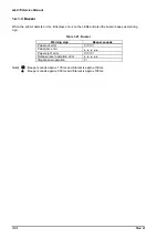
It blinks when the Micro Adjust function is enabled or the printer is in the head hot status.
*2 Paper Out (Red)
It is on when the printer is in the paper out status, and it is off when the printer is out of this status.
*3Tear Off/Bin (Green)
2 LEDs display the status of CSF bin selection when cut sheet is used. Only a right LED is on when
Bin1 is selected, only a left LED is on when Bin2 is selected, and both LEDs are on when the Card
mode is selected.
Both LEDs blinks when continuous paper is in the Tear-off position and both LEDs are off when
continuous paper is out of the Tear-off position.
*4Font (Green)
The status of Font selection is displayed by 3 Font LEDs.
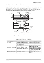
Table 1-26. LED Indicators
Содержание LQ 670 - B/W Dot-matrix Printer
Страница 1: ...EPSON IMPACT DOT MATRIX PRINTER EPSON LQ 670 SERVICE MANUAL SEIKO EPSON CORPORATION 4007875 ...
Страница 5: ...v REVISION SHEET Revision Issued Data Contents Rev A May 28 1997 First issue ...
Страница 114: ...Chapter 6 Maintenance 6 1 Preventive Maintenance 6 1 ...
Страница 116: ...LQ 670 Service Manual Rev A 6 2 Figure 6 1 Lubrication Points ...
Страница 122: ...LQ 670 Service Manual Rev A A 5 A 2 Circuit Diagram Figure A 2 C214Main Board Circuit Diagram ...
Страница 123: ...Appendix Rev A A 6 Heat Sink Q1 D51 Figure A 3 C214PSB Board Circuit Diagram ...
Страница 124: ...LQ 670 Service Manual Rev A A 7 Heat Sink Q1 D51 Figure A 4 C214PSE Board Circuit Diagram ...
Страница 125: ...Appendix Rev A A 8 A 3 Component Layout Figure A 5 C214 Main Board Component Layout ...
Страница 126: ...LQ 670 Service Manual Rev A A 9 Figure A 6 C214 PSB Board Component Layout Figure A 7 C214 PSE Board Component Layout ...
Страница 127: ...Appendix Rev A A 10 A 4 Exploded Diagram Figure A 8 Exploded Diagram ...
Страница 128: ...LQ 670 Service Manual Rev A A 11 Figure A 9 Exploded Diagram ...
Страница 129: ...Appendix Rev A A 12 Figure A 10 Exploded Diagram ...
Страница 135: ...EPSON SEIKO EPSON CORPORATION ...

