LQ-670 Service Manual
Rev. A
1-20
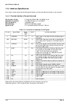
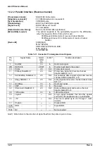
1.3.2.2 Parallel Interface (Reverse channel)
[Transmission mode]
: IEEE 1284 nibble mode
[Adaptable connector]
: 57-30360(Amphenol) or equivalent
[Synchronization]
: /STROBE pulse
[Handshaking]
: BUSY and /ACKNLG signals
[Signal Level]
: IEEE-1284 level 1 device
TTL compatible
[Data transmission timing]
: Refer to the IEEE-1284 specification
[Extensibility request]
: The printer responds to the extensibility request in the affirmative,
when the request is 00H or 04H, which mean;
00H:Request nibble mode of reverse channel transfer
04H:Request device ID in nibble mode of reverse channel
transfer.
[Device ID]
: [00H] [3AH]
MFG: EPSON;
CMD:ESCPL2,PRPXL24, BDC;
MDL;LQ-670;
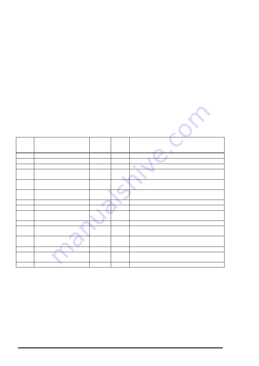
CLS:PRINTER;
Pin
No.
Signal Name
Return
GND
Pin
In/Out*
Function description
1
HostClk
19
In
Host clock signal
2
∼
9
DATA1
∼
8
20
∼
27
In
Parallel input data to the printer.
10
PtrClk
28
Out
Printer clock signal.
11
PtrBusy, DataBit-3,7
29
Out
Printer busy signal and reverse channel
transfer data bit 3 or 7.
12
AckDataReq, DataBit-2, 6
28
Out
Acknowledge data request signal and reverse
channel transfer data bit 2 or 6.
13
Xflag, DataBit-1, 5
28
Out
X-flag signal and reverse channel transfer data
bit1 or 5.
14
HostBusy
30
In
Host busy signal.
31
/INIT
30
In
Not used.
32
/Data Avail, DataBit-0, 4
29
Out
Data available signal and reverse channel
transfer data bit0 or 4.
36
1284-Active
30
In
1284 active signal.
18
Logic-H
---
Out
A high signal indicates that all other signals
sourced by the peripheral are in a valid state.
35
+5V
---
Out
This line is pulled up to +5V through 1.0 k
Ω
resistor.
17
Chassis
---
---
Chassis GND.
16,33,
19-30
GND
---
---
Signal GND.
15,34
NC
---
---
Not connected.
Note*):
In/Out refers to the direction of signal flow/from the printer’s point of view.
Table 1-21. Connector Pin Assignment and Signals
Содержание LQ 670 - B/W Dot-matrix Printer
Страница 1: ...EPSON IMPACT DOT MATRIX PRINTER EPSON LQ 670 SERVICE MANUAL SEIKO EPSON CORPORATION 4007875 ...
Страница 5: ...v REVISION SHEET Revision Issued Data Contents Rev A May 28 1997 First issue ...
Страница 114: ...Chapter 6 Maintenance 6 1 Preventive Maintenance 6 1 ...
Страница 116: ...LQ 670 Service Manual Rev A 6 2 Figure 6 1 Lubrication Points ...
Страница 122: ...LQ 670 Service Manual Rev A A 5 A 2 Circuit Diagram Figure A 2 C214Main Board Circuit Diagram ...
Страница 123: ...Appendix Rev A A 6 Heat Sink Q1 D51 Figure A 3 C214PSB Board Circuit Diagram ...
Страница 124: ...LQ 670 Service Manual Rev A A 7 Heat Sink Q1 D51 Figure A 4 C214PSE Board Circuit Diagram ...
Страница 125: ...Appendix Rev A A 8 A 3 Component Layout Figure A 5 C214 Main Board Component Layout ...
Страница 126: ...LQ 670 Service Manual Rev A A 9 Figure A 6 C214 PSB Board Component Layout Figure A 7 C214 PSE Board Component Layout ...
Страница 127: ...Appendix Rev A A 10 A 4 Exploded Diagram Figure A 8 Exploded Diagram ...
Страница 128: ...LQ 670 Service Manual Rev A A 11 Figure A 9 Exploded Diagram ...
Страница 129: ...Appendix Rev A A 12 Figure A 10 Exploded Diagram ...
Страница 135: ...EPSON SEIKO EPSON CORPORATION ...

