background image

OSCI-MODE

 =


DISPLAY EDITOR

INTERFACE

 =

C-TEST MODE

 =

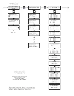
1   DISPLAY LINE 1

  *

1 [ REACTIVE POWER     ]
2

   ACTIVE POWER  

Σ


3   APPARENT POWER 

Σ


Σ

2   DISPLAY LINE 2

  *

1   REACTIVE POWER  
2

 [ ACTIVE POWER   

Σ

  ]  

3   APPARENT POWER 

Σ


Σ

3   DISPLAY LINE 3

  *

1   REACTIVE POWER 
2

   ACTIVE POWER   

Σ


3 [ APPARENT POWER 

Σ

 ]


Σ

4   BASIC SETTINGS
  
     [ NO ]

BACK TO 1

BACK TO 1

BACK TO 1

BACK TO 1

1 U/I-1

2 U/I-2

3 U/I-3

4 U-1...3

5  I-1...3

- 42 -

1  PROTOCOL COM 1

       [ MODBUS RTU ]

1   C-TEST

     [ YES ]

2  BAUDRATE COM 1
 
       [ 9600 / NONE  ]

2  MMI- TYP
 
       [ MMI8003 ]

3  BUS-ADRESS COM 1

       [ 1 ]


3  NUMBER MMI

       [ 1 ]


4  ASCII-REPET. INTERVAL

      [ 10 ] sec.


4  FAULT C  OFF

      [ NO ]


5   PROTOCOL COM 2
  
     [ MODBUS-RTU ]

5   C -FAULT (+)
  
     [ 140 ] %

6   BAUDRATE COM 2


[ 38400 / NONE ]

6   C-FAULT (-)


[ 60 ] %

7   BUS-ADRESS COM 2
   
     [ 1 ]

7   TEST ATTEMPTS
   
     [ 6 ]

8  DEFECT- C- FLASH
   
     [ NO ]

9   TEST-RUN
   
     [ NO ]

10   START
11  TEST-RUN
12  BREAKUP

13  C-TEST  - TEST-RUN

[

[C01] ->    ?           ?
[C02] ->    ?           ?
[C03] ->    ?           ?

14   TIME-STAMP / TEST
   
   05.05.2016    10:00:05

15   MEMORY
   
   RESET    [ NO ]

Содержание BR 7000

Страница 1: ...ctor Controller BR 7000 Manual Version 4 0 E Power Factor Controller BR 7000 Auto Program Manual Service Enter OK Power Quality Solutions HELP ESC 0 869 IND 0 869 IND 0 869 IND L1 L2 L3 1 2 3 4 AUTO M...

Страница 2: ...f different grid parameters 3 display arrangements with each up to 12 different parameters can be shown simultaneously All values displayed can be recorded for a later processing The step display deli...

Страница 3: ...Fault memory p 22 Section 11 EXPERT MODE 11 1 Expert Mode 1 p 23 11 2 Expert Mode 2 p 25 Section 12 OSCI MODE p 26 Section 13 DISPLAY editor p 26 Section 14 Maintenance and warranty p 26 Section 15 IN...

Страница 4: ...the programming menu by an additional ESCape button The usage of a fully graphic support display allows an additional Oscilloscope Mode where the phases half waves of voltage and current can graphical...

Страница 5: ...separator The device must not be operated without protective earth contactor connected Before connecting the BR7000 it has to be checked that all connections are at zero potential current transformer...

Страница 6: ...puts K1 K15 to the capacitors complies to the selected connection variant and the desired CONTROL MODE Programming point 2 Especially in Mixed Mode where some outputs are used for single phase capacit...

Страница 7: ...polated balance assumed Measuring complies with conventional measuring for switching of three phase capacitors Use CONTROL MODE 5 BR7000 Alternative 3 single phase measuring as alternative 2 but with...

Страница 8: ...sum current converters the overall conversion ratio is entered Caution The secondary clamps of the CT have to be short circuited before current leads are iterrupted BR7000 BR7000 in High Voltage Appl...

Страница 9: ...before an impending switching step A double arrow symbolizes switching of several branches The sigma sign indicates the three phase value mean value resp activated three phase capacitors Alarm relay...

Страница 10: ...be displayed s table below Action Display Unit in Bargraph 3 phase possible ENTER 1 LINE VOLTAGE V x ENTER 2 CURRENT A apparent active reactive x ENTER 3 REACTIVE POWER kvar x ENTER 4 ACTIVE POWER kW...

Страница 11: ...itor INTERFACE Mode C TEST MODE and back to Auto L1 V 0 4 I 0 5 L2 V 1 4 I 0 8 L3 V 1 4 I 0 7 L1 N 233 V L2 N 233 V L3 N 233 V 2 CURRENT 8 TEMPERATURE 29 C 1 LINE VOLTAGE 9 HARMONICS 3 2 STROM 2 STROM...

Страница 12: ...in case of switching of single phase capacitors L N Allocation of switching outputs K1 K15 to the capacitors according to the selected connection variant and the desired CONTROL MODE Especially in Mix...

Страница 13: ...eps 3 Three phase capacitors P1 1 2 3 4 5 P2 6 7 8 9 10 P3 11 12 13 14 15 Output 1 5 Output 6 10 Output 11 15 meas voltage L1 meas voltage L2 meas voltage L3 PE N K 5 K10 K15 F1 6 3AT F1 6 3AT F1 6 3A...

Страница 14: ...via LAN cables COM2 at BR7000 Connection of BR7000 compare Control Mode 5 CONTROL MODE 9 3 phase measuring max 3x5 single phase capacitors L N correspond to Control Mode 1 but remote measurement via M...

Страница 15: ...e present the user may define a special one in control series ED see Annex 4 Control series editor 7 CONTROL PRINCIPLE The control preference may be selected here SEQUENTIAL connection LOOP connection...

Страница 16: ...arget cos phi only available if selected under 10 14 MEASURING VOLTAGE L L 400 V 50 760 V Programming of measuring voltage The values programmed here always refer to the voltage at the clamps of the c...

Страница 17: ...oller K21 will respond At the same time the display shows the cause of the alarm over temperature When the temperature drops again the required branches are automatically re connected in steps Selecti...

Страница 18: ...ications are for example changing of target cos phi switch over of current transformer or switch over the switching times By triggering a 110 230V signal at the external input the 2nd parameter set is...

Страница 19: ...anel builder optimum values for the system if the controller has been delivered together with the PFC system If the controller has been delivered ex works this point corresponds to the default setting...

Страница 20: ...ODE 2 MIXED MODE and must be obeyed without exeption s example next page Section 8 ALARM RELAY ERROR MESSAGES The contact of the alarm relay K21 is closed during normal operation and opens in case of...

Страница 21: ...EL K02 L1 C2 1 REL K07 L2 C2 2 REL K12 L3 C2 3 REL K03 L1 C3 1 REL K08 L2 C3 2 REL K13 L3 C3 3 REL K04 L1 C4 1 REL K09 L2 C4 2 REL K14 L3 C4 3 REL K05 C1 REL K10 C2 REL K15 C3 L1 R L2 S L3 T 3 x 4 sin...

Страница 22: ...fined continued switching via ENTER for the following states AUTO Automatic normal operation The relevant output is marked by a capacitor symbol FIXED The output is continuously connected e g for fixe...

Страница 23: ...n Display Unit 3 phase ENTER 1 max VOLTAGE in V L1 L3 ENTER 2 max CURRENT in A L1 L3 ENTER 3 max REACTIVE POWER in kvar L1 L3 ENTER 4 max ACTIVE POWER in kW L1 L3 ENTER 5 max APPARENT POWER in kVA L1...

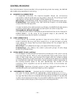
Страница 24: ...anged for special applications 6 SWITCHING POWER max 100 kvar multiple of smallest step This factor specifies the maximum power which may be switched in one switching step It can be used to control th...

Страница 25: ...nnection of the voltage with or without Neutral has to be programmed here in every case 14 POWER 1 STAGE 0 255 0 2550 0 25500 kvar The range of the power for the 1st stage can be changed here e g High...

Страница 26: ...r 3 ALARM RELAY Delay time 10 min 1 255 min 4 UNDER VOLTAGE 50 20 95 If the measuring voltage falls below this value all steps are simultaneously switched off 5 OVER VOLTAGE 115 105 140 If the measuri...

Страница 27: ...the warranty period all warranty claims lapse To be reached via button operation mode in the main menu In Display editor the values that will be permanently shown in the display mode 1 Out of all 50 m...

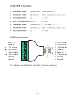
Страница 28: ...structure All devices are connected to one line in parallel Example connection of several BR7000 to a PC This can be done via standard patch cables LAN cable NOTE This is not a LAN network Max cable l...

Страница 29: ...COM2 MODBUS RTU MODBUS 6 BAUDRATE COM2 38400 None 9600 256000 None Odd Even 7 BUS ADRESS COM2 1 1 255 MASTER 28 1 8 Data A 1 5V internal Data B 2 5V internal 5V internal 3 24V internal 5V internal 4 D...

Страница 30: ...rmined In case this value is reached an error message is displayed 7 TEST ATTEMPTS 6 3 25 A C error message is displayed only after these given numbers of consecutive measurements have indicated an er...

Страница 31: ...for the longest time is connected next Advantage even utilization of stages increase of life time of system Disadvantage only effective for control series with groups of same stage power long reactio...

Страница 32: ...rallel operation same number of steps in each system or both systems are operated in master slave mode First all stages of the first system then all steps of the second system Coupling of 2 power fact...

Страница 33: ...ol series in case the required control series is not available In PROGRAM MODE the last control series control series ED has to be selected and confirmed by ENTER This adds an additional menu point to...

Страница 34: ...current in same phase See above Current in measuring range Line interruption Wrong current converter factor Current transformer short circuited Check ratio of current transformer 1 5A Go through measu...

Страница 35: ...control mode and END STOP Check programming and the capacitance of the smallest stage Check programming and the values of the current converters Check programming of the control series and the capacit...

Страница 36: ...several timers Manual operation Fixed steps skip steps Zero voltage release BR 7000 110 440 V 10 50 60Hz 3 30 440 V L N 50 760V L L 3 X 5 1A selectable 5 W 50 mA 10mA 15 relays freely programmable for...

Страница 37: ...voltage current frequency reactive active apparent power missing kvar temperature THD V THD I selection via display editor 3 31 harmonics of U and I display also in or as bar graph graphical display o...

Страница 38: ...S THD I CLOCK DATE Q OFFSET CONTRAST BASIC SETTINGS Default setting ENGLISH 1 3x5 single phase capacitors L N 1000 A 5 A 3 x 5 1 INTELLIGENT 25 00 kvar 0 98 IND SUPPLY L L 400 V L N 230V NO 40 90 Hz 4...

Страница 39: ...elay C FAULT C FAULT OVERCOMPENSATED UNDERCOMPENSATED Switch operation RESET Operating time RESET INTERFACE Protocol COM1 Baudrate COM1 Bus adress COM1 ASCII transm interval Protocol COM2 Baudrate COM...

Страница 40: ...3 16 kvar N 52 kvar 6 CONTR SERIES L1 N 1 1 1 1 1 1 L2 N 1 1 1 1 1 1 L3 N 1 1 1 1 1 1 7 FREQUENCY 50 Hz 7 CONTR PRINC 3 INTELLIGENT 22 MESSAGE RELAY 1 OFF 23 EXT INPUT 1 NO 8 TEMPERATURE 8 POWER 1st S...

Страница 41: ...background colour are active only in case of certain other settings If not needed they are not displayed Operating diagram Brief programming Power Factor Controller BR 7000 SERVICE 1 max VOLTAGE L1 N...

Страница 42: ...SWORD 0 6 3 4 3 5 OVERVOLTAGE LIMITING VALUE 460 V 115 6 OVERCOMPENSATED Q DIFF 7 UNDERCOMPENSATED Q DIFF 8 SWITCH OPERATION C1 RESET NO until C15 RESET NO 9 OPERATION TIME C1 RESET NO until C15 RESET...

Страница 43: ...ACK TO 1 1 U I 1 2 U I 2 3 U I 3 4 U 1 3 5 I 1 3 42 1 PROTOCOL COM 1 MODBUS RTU 1 C TEST YES 2 BAUDRATE COM 1 9600 NONE 2 MMI TYP MMI8003 3 BUS ADRESS COM 1 1 3 NUMBER MMI 1 4 ASCII REPET INTERVAL 10...

Страница 44: ...onverter to connect the devices via RJ45 standard cable Accessories Data Logger DataLog SD for BR6000 and BR7000 Recording of all grid and system parameters on a SD memory card Multi Measuring Devices...

Отзывы: