- 15 -
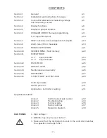
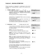
=== PROGRAM-MODE ===
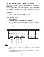
9 TARGET COS PHI
[ 0.98 ind ]
( 0.1 ind ... 0.1 cap )
By setting the target cos phi, the power factor to be
attained via the PF correction is defined.
Sequential setting of L1 ... L3 via
é
/
ê
,
Save and continue with ENTER.
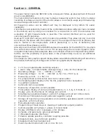
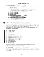
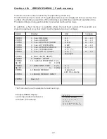
10 TARGET 2nd cosPhi [ NO ]
( 1...4 )
1: NO
( no 2nd target cosPhi,
continue with 14 )
2: Timer
( 2nd cos Phi - activated by timer,
scheduler with 12,13 )
3: Energy supply (2nd target cos-phi - activated by
Energy-supply)
4: Low load
(2nd target cos Phi - activated by
low load (smaller than 3x 1st stage)
11 TARGET 2nd cosPhi [ 0.9 IND ]
(0.1 ind ... 0.1 cap )
Set point for the 2nd target cosPhi
(only available if selected under 10)
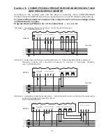
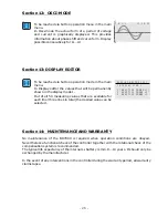
12 SWITCH ON TIME
ϕ
2
[ HH:MM:SS ]
Switch-on time of the timer for the 2nd target-cos phi
( only available if selected under 10 )
13 SWITCH OFF TIME
ϕ
2
[ HH:MM:SS ]
Switch-off time of the timer for the 2nd target-cos phi
( only available if selected under 10 )
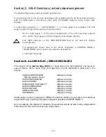
14 MEASURING VOLTAGE
L-L [400]V ( 50...760) V
Programming of measuring voltage.
The values programmed here always refer to the
voltage at the clamps of the controller !
Selection via
é
/
ê
. Save / continue with ENTER
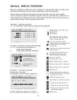
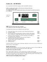
15 V-CONVERTER
[ NO ]
(300V-380kV / 440V )
When a measuring-voltage converter (e.g. for HV-
measurement) is used, its conversion ratio is to be
programmed here.
Selection via
é
/
ê
. Save / continue with ENTER
16 FREQUENCY [40...90] Hz (50Hz, 60Hz, 16,7Hz)
Use fix-frequency in grids with difficult voltage form
(harmonics)
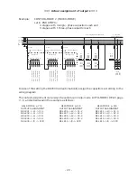
17 CONNECTING TIME: [ 40 ] sec.
( 1 sec. ... 130min.)
The time between connecting the capacitors to increase
the momentary network capacitance. It should be noted
that in practical operation the real connection time is
affected by the discharge time (locking time).
Selection via
é
/
ê
. Save / continue with ENTER
12 SWITCH ON TIME
ϕ
2
ON [16]: 00 MO-FR
OFF 07 : 00 MO-FR
15 V-CONVERTER
[NO]
PROGRAM-MODE [3]
PROGRAM-MODE
PROGRAM-MODE
10 TARGET 2nd cos
ϕ
[ SUPPLY ]
PROGRAM-MODE
9 TARGET cos
ϕ
[ 0.980 IND]


