Design of ASCII-transmission protocol
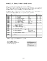
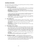
The following data are send one after the other:
U1= 223 V
U2= 222 V
U3= 220 V
I1= 100 A
I2= 100 A
I3= 100 A
PF1= +0.949
PF2= -1.000
PF3= +1.000
Q1= 100 kvar
Q2= 100 kvar
Q3= 100 kvar
P1= 100 kW
P2= 100 kW
P3= 100 kW
S1= 100 kVA
S2= 100 kVA
S3= 100 kVA
OUT1= -----
OUT2= -----
OUT3= -----
(active stages)
Application: Controller coupling
Application example:
Two separate systems operate at two transformer feed ins; it exists one coupling with
coupling switch between both systems.
a) Coupler opened; both systems operate self-governed;
b) Coupler closed: with the controller coupling both systems are operated symmetrically
in parallel operation (same number of steps in each system) or both systems are
operated in master/slave mode. (First all stages of the first system, then all
steps of the second system)
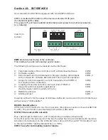
Coupling of 2 power factor controllers BR7000 is done via their interface COM2:
The operation mode coupling operation (parallel operation resp. master-slave-operation)
is selected in the program-mode under 23 EXTERNAL INPUT.
The 110...230V~ signal "coupling switch closed“ has to be directed to the external input
of a controller (master). The programming has to be performed only on this controller.
No more settings required !
- 31 -
COM 2
COM 2
Power Factor
Controller
BR 7000
Auto
Program
Manual
Service
Enter
OK
Power Quality Solutions
HELP
ESC
cos
ϕ
Power Factor
Controller
BR 7000
Auto
Program
Manual
Service
Enter
OK
Power Quality Solutions
HELP
ESC
cos
ϕ

