AFTER INSTALLING THIS UNIT PLEASE PASS ONTO END USER
DO NOT THROW AWAY
18
05
Control Display
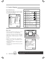
1. Flow rate indicator
2. eBus connection indicator
3. Fan indicator
The display shows a bar chart
(flow rate indicator) of the current
ventilation rate.
This eBus indicator appears when
the eBus connection is active; if it
is not visible, no communication is
possible between the control unit
and the Slimline appliance.
This ventilation indicator appears
when the fans in the appliance are
running.
4. Fault symbol
5. Filter message
6. Current time block
This fault symbol appears when an
appliance fault has occurred.
When the text “Filter” appears on
the control unit display, the filters in
the appliance must be cleaned or
replaced.
This indicates in what
(preprogrammed) time interval the
appliance is. When the manual
control key (
) is activated, the
time interval picture disappears
and is replaced by the message
“Manual”. When the ventilation flow
rate is modified temporarily using
the right-hand setting knob, the
time interval picture disappears
and is replaced by the message
“Temporary”.
7. Current day
8. Appliance selection
9. Current date (day/month/
year) and time
The current day is shown at this
position.
Pressing the appliance selection
key calls up a menu in which the
appliance can be selected that is
connected to the control unit.
The current date and time are
shown at this position. It is
important for proper performance
of the appliance that the time is set
correctly.
A
B
1
2
3
The supply and extract
fans are running at
30 m
3
/h or they are
stopped (step 1)
The supply and extract
fans are running in
ventilation mode 1
(step 2)
The supply and extract
fans are running in
ventilation mode 2
(step 3)
The supply and extract
fans are running in
ventilation mode 3
(step 4)
A = Flow rate indicator
B = 4-way switch
Содержание Slimline 150
Страница 1: ......
Страница 31: ...AFTER INSTALLING THIS UNIT PLEASE PASS ONTO END USER DO NOT THROW AWAY 30 07 Maintenance...


