


36167-1-0316
Page 73
IpI ELECTRONIC SYSTEM OpERATINg INSTRUCTIONS
5.25 vDC ELECTRONIC CONTROL vALvE
The electronic control valve system includes the ability to switch
the pilot from a standing pilot mode to an intermittent pilot mode.
•
IpI Mode
- In the Intermittent Pilot mode, when the
fireplace is turned oN, it will cause spark to the pilot,
light the pilot, then allow the burner to light. When the
fireplace is turned to oFF, both the burner and pilot will
be oFF.
•
CpI Mode
- In the Continuous Pilot mode, the pilot
remains oN continuously even when the burner is
turned oFF.
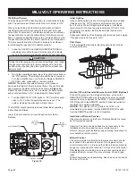
NOTICE
: A small toggle switch is located on the front of the
module tray that is used to switch from IPI (left) to the CPI (right).
See figure 79.
When the fireplace is turned to oN, the electrical current will
energize a spark to the pilot igniter. once the pilot sensor heats
up (after a few seconds), the valve will be energized, allowing
gas to flow to the burner.
1. Follow the SAFeTY and LIGHTING INSTRUCTIoNS for
Intermittent Pilot controls found in this manual, and on labels
found in the control compartment located in the lower cavity
of the fireplace.
2. During the operating season (or in power outage periods),
it is recommended that the pilot remain in the CPI (standing
pilot mode) to reduce cold start issues, and/or conserve
battery backup power during a power outage.
3. The gas valve has inlet and outlet pressure taps as shown in
figure 79.
Refer to page 13 for gas pressure requirements.
NOTICE
:
The gas control has a manual HI/Lo flame adjustment
knob (regulator) that allows you to increase or decrease the
height of the burner flame.
See figure 79.
Rotate the HI/Lo
knob counterclockwise to
“
HI
”
to increase the flame height, and
clockwise to
“
Lo
”
to decrease the flame height.
OpTIONAL REMOTE CONTROLS
optional remote controls are available for use with this fireplace.
It is recommended that the remote receiver be placed either in
a wall outlet box with extended wiring, on the fireplace hearth,
behind the left side surround panel, or in the control compartment
area as far forward in the insert as possible.
The placement options for the remote receiver are given to allow
flexibility, however battery life will be extended when the receiver
is placed in cooler areas.
To connect the remote receiver to the fireplace, first disconnect
the oN/oFF switch wires from the white and green wire
connectors and connect the wires from the remote receiver to the
green and white wire connectors.
See figure 79.
Follow the instructions included with the remote control for
programming and other operational information.
figure 79
Содержание DVCD32FP3-2
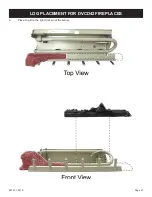
Страница 41: ...36167 1 0316 Page 41 1 Place Log A on the left front pin of the burner LOG PLACEMENT for DVCD32 fireplaces ...
Страница 42: ...36167 1 0316 Page 42 2 Place Log B on the right front pin of the burner LOG PLACEMENT for DVCD32 fireplaces ...
Страница 44: ...36167 1 0316 Page 44 4 Place Log D onto the rear log support LOG PLACEMENT for DVCD32 fireplaces ...
Страница 48: ...36167 1 0316 Page 48 Log placement is complete LOG PLACEMENT for DVCD32 fireplaces ...
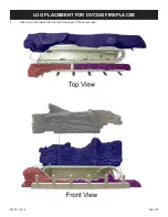
Страница 51: ...36167 1 0316 Page 51 1 Place Log A on the left front pin of the burner LOG PLACEMENT For DVCD36 fireplaces ...
Страница 52: ...36167 1 0316 Page 52 2 Place Log B on the right front pin of the burner LOG PLACEMENT For DVCD36 fireplaces ...
Страница 54: ...36167 1 0316 Page 54 4 Place Log D onto the rear log support LOG PLACEMENT For DVCD36 fireplaces ...
Страница 57: ...36167 1 0316 Page 57 Log placement is complete LOG PLACEMENT For DVCD36 fireplaces ...
Страница 60: ...36167 1 0316 Page 60 1 Place Log A on the left front pin of the burner LOG PLACEMENT for DVCD42 fireplaces ...
Страница 61: ...36167 1 0316 Page 61 2 Place Log B on the right front pin of the burner LOG PLACEMENT for DVCD42 fireplaces ...
Страница 62: ...36167 1 0316 Page 62 3 Place Log D onto the rear log support LOG PLACEMENT for DVCD42 fireplaces ...
Страница 67: ...36167 1 0316 Page 67 Log placement is complete LOG PLACEMENT for DVCD42 fireplaces ...


