


36167-1-0316
Page 34
Dvvk-4f fLEX vENT INSTRUCTIONS
CAUTION
Sharp edges. To avoid injuries, wear safety gloves when
handling the flex vent components.
The
Dvvk-4f fLEX vENT kIT
includes the following
components:
•
(1) Horizontal Termination Cap
•
(1) 4-foot section of Flex vent with spacers (4” flue/7” outer
pipe)
•
(1) 4-inch diameter Flue adapter collar
•
(1) 7-inch diameter outer Vent adapter collar
•
(1) Wall Firestop/Thimble Assembly
•
Hardware pack that includes band clamps and screws
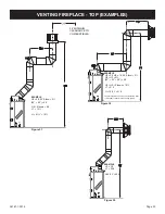
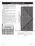
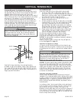
Flex venting can be installed either vertically or horizontally off
of the DVCD Series fireplaces. When installing a horizontal vent
run from top connections, maintain at least ½ inch rise for every
12 inches of vent run. When venting horizontal off the rear vent
connections, allow a minimum rise of 2 inches. Refer to Figure 52
when mounting termination near vinyl siding.
Attention: Always stretch and secure venting with wire or metal
strapping to ensure that the horizontal runs do not sag.
If space permits, it is generally easier to attach venting in the top
vent configuration.
Vent connections should overlap a minimum of 1 inch for proper
sealing.
Always follow the general venting requirements for vent terminal
location, vent lengths, and clearance to combustible materials.
INSTALLATION
1. Unpack vent components and check that all items are
included.
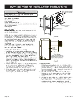
2. Verify the spacer springs are located around the flue vent
at 8-inch intervals along its length. See Figures 58 and 59.
If the spacer springs are not installed, stretch the spacer
springs to about 15 inches long and wrap them around the
flue, then interlock the ends of each spring at 2 inches.
maintain equal distance between spring spacers.
8
(203 mm)
8
(203 mm)
8
(203 mm)
4 FLEX
VENT PIPE
SPACER
SPRING
””
”
”
”
figure 58
SPACER
SPRINGS
FLEX FLUE PIPE
FLEX OUTER VENT
figure 59
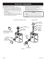
3. Remove the 6-⅝ inch diameter Vent collar from the fireplace.
Replace this collar with the 7 inch diameter Flex Vent
adapter collar provided with the vent kit.
4. Slide the Flex Vent flue pipe into the outer Flex Vent pipe.
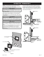
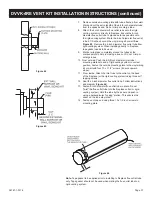
5. Install the Wall Firestop/Thimble assembly as required
through the wall. Refer to the venting charts in the fireplace
manual to determine the proper height and size of the vent
opening. The minimum opening should be 9 inches wide by
11 inches high. The minimum combustible clearance from
the horizontal vent is 1 inch from sides and bottom, and 3
inches above the vent pipe. See Figure 60.
TOP OF VENT
COMBUSTIBLES NOT
ALLOWED IN SHADED
AREA
4” DIAMETER
FLUE
7” DIAMETER
INTAKE VENT
figure 60
6. In most cases, after determining the length of the vent that
is needed, it may be easier to install the flue and outer vent
pipes to the Termination Cap first, then from the outside,
feed the venting through the wall to the fireplace.
7. If the venting is to long, trim off any excess vent before
attaching the vent end connectors.
CAUTION
Do not use force when installing the Horizontal Vent
Termination into the flex venting. Always stretch venting out
first, then cut off excessive vent material prior to sliding the
vent termination into the flue and inlet venting. Forcing the
termination cap into the flex venting will deform the flue venting,
which will restrict the exhaust gases, and cause improper
operation of the fireplace.
Содержание DVCD32FP3-2
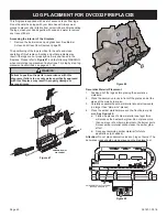
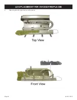
Страница 41: ...36167 1 0316 Page 41 1 Place Log A on the left front pin of the burner LOG PLACEMENT for DVCD32 fireplaces ...
Страница 42: ...36167 1 0316 Page 42 2 Place Log B on the right front pin of the burner LOG PLACEMENT for DVCD32 fireplaces ...
Страница 44: ...36167 1 0316 Page 44 4 Place Log D onto the rear log support LOG PLACEMENT for DVCD32 fireplaces ...
Страница 48: ...36167 1 0316 Page 48 Log placement is complete LOG PLACEMENT for DVCD32 fireplaces ...
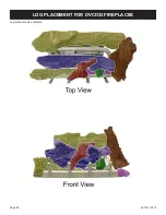
Страница 51: ...36167 1 0316 Page 51 1 Place Log A on the left front pin of the burner LOG PLACEMENT For DVCD36 fireplaces ...
Страница 52: ...36167 1 0316 Page 52 2 Place Log B on the right front pin of the burner LOG PLACEMENT For DVCD36 fireplaces ...
Страница 54: ...36167 1 0316 Page 54 4 Place Log D onto the rear log support LOG PLACEMENT For DVCD36 fireplaces ...
Страница 57: ...36167 1 0316 Page 57 Log placement is complete LOG PLACEMENT For DVCD36 fireplaces ...
Страница 60: ...36167 1 0316 Page 60 1 Place Log A on the left front pin of the burner LOG PLACEMENT for DVCD42 fireplaces ...
Страница 61: ...36167 1 0316 Page 61 2 Place Log B on the right front pin of the burner LOG PLACEMENT for DVCD42 fireplaces ...
Страница 62: ...36167 1 0316 Page 62 3 Place Log D onto the rear log support LOG PLACEMENT for DVCD42 fireplaces ...
Страница 67: ...36167 1 0316 Page 67 Log placement is complete LOG PLACEMENT for DVCD42 fireplaces ...


